@rogloh said:
Yeah what I was thinking is that the TV & AVR can probably tolerate the occasional excess samples here and there (and just drops them if the buffer is full) but can't deal with a case when samples are missing due to underflow. So losing samples by playing the buffer slightly faster at the sink than the arrival rate using the locally regenerated clock eventually leads to underflows causing it to mute and rebuild the buffer hoping things will stabilise afterwards.
But that's what the regen packet is for The clock sync is supposed to be exact with no slippage at all (for Hi-Fi audio, dropped or repeated samples would be unacceptable).
So long as it's computed perfectly and never accumulates error due to rounding/truncation etc it should be fine. The RasPi does vary the CTS very slightly by the way.
Also the P2 PLL is not going to be able to get so close to this particular VIDEO_CLKFREQ frequency. Using the MVS clock of 24MHz and multiplying by 14 is likely to be closer (336MHz an exact integer) and be easier to achieve with 20MHz P2 XTALs although it will affect your refresh rate slightly and some pitches altered perhaps depending on the resampling you do. I'm going to try that too and report the results here below. The N/CTS would fit nicely with 336MHz as it is also an exact integer multiple of 48000 (specifically 7000).
I am somewhat convinced part of why they use a faster crystal on the AES is specifically to edge the video frequencies closer to NTSC standard. You could try using the MVS clocks I guess. Everything's done under the assumption that the PLL is running exactly, so it shouldn't really matter that it doesn't.
Didn't help with MVS clock - see above result. It might be some resampler computation being affected if it resamples from 44.1 to 48 using this, not sure. You'd have a better idea what the impact would be.
Yeah I may try that. The RasPi sends 44.1kHz audio and also sets the SPDIF channel status to 48kHz and it works although it might be slightly noisy too (I only had a short test speaker sample to listen too and I was more interested in capturing the HDMI than listening to the quality). At some point I'd like to get it to output real 48kHz source material somehow. I'll have to look for something to install like VLC on that device which I can use for playback of other material if it is available on Ubuntu ARM64, or figure out what else I can use.
You'd need to actually go to some accursed settings panel to set the mixer rate to 48k, it ought not to matter what the source format is. I think, anyways. Or maybe GNOME devs decided that no one actually wants to change their mixer rate and it doesn't exist...
Yeah will probably have to dig into it at some point unfortunately...
@rogloh said:
Yeah what I was thinking is that the TV & AVR can probably tolerate the occasional excess samples here and there (and just drops them if the buffer is full) but can't deal with a case when samples are missing due to underflow. So losing samples by playing the buffer slightly faster at the sink than the arrival rate using the locally regenerated clock eventually leads to underflows causing it to mute and rebuild the buffer hoping things will stabilise afterwards.
But that's what the regen packet is for The clock sync is supposed to be exact with no slippage at all (for Hi-Fi audio, dropped or repeated samples would be unacceptable).
So long as it's computed perfectly and never accumulates error due to rounding/truncation etc it should be fine. The RasPi does vary the CTS very slightly by the way.
And that should be the case! Check out the resampler logic. It uses a phase accumulator - whenever the integer part is greater than one, an input sample must be consumed. To stop rounding error, the somewhat misnamed "dejitter" thing resets the phase to zero at the exact point where it should (i.e. when you'd otherwise have your $FFFF_FFFF almost-one rounding error)
Yeah I think I'll have to take a deeper look to try to see what is going on. Been avoiding it a bit.
One thing I can't see is the long term audio sample buffer size effect due to capture size limitations of 32MB of PSRAM. With NeoVGA and 10 bit TMDS internal capture I get a brief sub-second snapshot consuming 5 bytes per pixel with on the fly compression into PSRAM. Ideally I could capture for several seconds which might show drop outs or accumulating sample loss. To do that I'd need to decode the HDMI data stream on the fly and only save the audio stuff into PSRAM instead of everything - very difficult to decode with the internal TMDS capture, but maybe doable with the external RGB capture directly to longs which I could compare to known delimiters like DataGuard patterns on the fly. I guess I could try to use the TFP401 board and run your code on a different P2 EVAL board instead of the Edge and this would allow the external capture of your audio but will take a while to sort out and I'm not sure I'll resort to that yet.
@Wuerfel_21 Could there be any scan lines ever generated due to some reason or another where don't call your build_audio function or don't have it complete to the point where it adds to the "resample_phase_int" variable when it should? I thinking special cases like AVI infoframe sending or special vsync line handling for example. If that were the case it could leak audio samples in time at the frame rate, and I may not see it in my rather short captures but it could deplete over a second or two during hundred of frames transmitted @ 60Hz thereby draining potentially hundreds of FIFO audio samples fairly quickly at the HDMI sink perhaps causing these gaps in my AV gear while it tries to refill the emptied buffer...? This is just a thought, still working my way through your code paths and I'm understanding more of it as I go.
I suspect other non-HIFI oriented devices like simple HDMI monitors under similar circumstances might just fill in lost samples with previous values or extrapolate to keep the buffer streaming when it's about to underflow and this loss is being hidden/ignored.
It'd be interesting to try to deliberately lose some audio samples and see how these devices behave when you know there is some loss. If they continue on playing audio out blindly you'll know for sure they won't exhibit this issue I somehow have with my stricter gear.
I just added a "drvnot #0" to the sample creation process to toggle a pin when each audio sample is encoded individually in the HDMI data islands. Then I used a neighbouring smartpin in "Event Ticks" counting mode to count the time in P2 clocks at which point 48000 edge transitions have been detected on that pin and printed it out.
I'm seeing fairly stable results that only vary by less than one scan line interval (which is 10750 P2 clocks) in each 1 sec detection of 48000 samples. Based on the fact that we should be emitting a sample every 7049 P2 clocks, then 48000*7049 = 338352000 P2 clocks which is close the to number below.
So it doesn't look like your repository samples are ever being missed in noticeable quantities by failing to poll the repo pin sufficiently often in the code. I was hoping I might have seen several missing polled samples that would have increased the time to emit 48000 edges by not decrementing the resample phase when it should to allow the code to send another packet at the earlier time. I could try to increase the sampling duration in case it somehow degrades over longer timeframes but I doubt it would change anything here unless some element of execution timing randomness creeps in every now and again.
The P2 clock is assumed to be 338.349606MHz based on the CON block constants, although the computed PLL settings for the clock mode (0x012CCAFB) would actually make it run at 338.333333 MHz if it has a perfect 20.000000 MHz crystal which it won't. That crystal difference won't change the P2 clock numbers below but does mean we don't get exactly 48000 samples per second sent over HDMI - it will be out a little bit, but should follow the N/CTS settings at least.
.dosp         ' Create an output sample using cubic resampling
              sub scantimecomp,#6+6 ' dosp (cubic)
              call scanfunc

              getword u1,resample_phase_frac,#1
              mov u2,u1
              mul u2,u1
              shr u2,#16
              mov u3,u2
              mul u3,u1
              shr u3,#16
              drvnot #0  '<<---- added this to probe HDMI audio sample creation
Here's what I do in the main COG while audio samples are being sent out in vgatest.spin2
 send("Press a key to sample",13,10)
 repeat
    uart.rx()
    pinstart(2,P_EVENTS_TICKS|P_MINUS2_A, 48000,2)
    repeat until PINR(2)
    x:=rdpin(2)
    send("clks for 48000 samples: ",f.dec(x),13,10)
Result:
( Entering terminal mode. Press Ctrl-] or Ctrl-Z to exit. )
Press a key to sample
clks for 48000 samples: 338349397
clks for 48000 samples: 338351999
clks for 48000 samples: 338353781
clks for 48000 samples: 338346527
clks for 48000 samples: 338345835
clks for 48000 samples: 338353263
clks for 48000 samples: 338346475
clks for 48000 samples: 338351211
clks for 48000 samples: 338353343
clks for 48000 samples: 338342789
clks for 48000 samples: 338350035
clks for 48000 samples: 338349653
clks for 48000 samples: 338346895
clks for 48000 samples: 338350978
@rogloh said:
So it doesn't look like your repository samples are ever being missed in noticeable quantities by failing to poll the repo pin sufficiently often in the code. I was hoping I might have seen several missing polled samples that would have increased the time to emit 48000 edges by not decrementing the resample phase when it should to allow the code to send another packet at the earlier time. I could try to increase the sampling duration in case it somehow degrades over longer timeframes but I doubt it would change anything here unless some element of execution timing randomness creeps in every now and again.
That could be tested for by putting the drvnot into the audio_poll_repo function and making sure there is never more than 6048 cycles between polls (the vgatest tone generator should write once every 6048cy exactly, not sure about actual OPNBcog). I don't think there's time for adding instructions there, so you'd have to write a little workalike that uses the same number of instructions.
Will try that later, have to go do something outside now.
There's certainly something up with sample TX jitter:
Not sure if that is spec-violating amounts of TX jitter...
Also, this is actually with increased poll rate, which doesn't seem to make a difference to this, but for completeness, to get that, change the code below .serloop to
It's working now on my Plasma TV! A pure solid tone. Happy Days. That was the issue. It doesn't like zero sample packets which would obviously create jitter. This is awesome.
I'm gonna try it on my AVR but I think it will work there too.
Don't celebrate early, it has to work in the actual application, too. Solid test tone is a good step though. Also need to think about how I'm going to refactor all these hacks into something nice
For those of us playing along at home, this has been a great thread! Congrats! To paraphrase Capt. Mal, You've done the impossible and that makes you mighty!
Could someone please do a brief summary of why HDMI audio was not working and why it is now, in fairly simple terms? EDIT:
Or how to guarantee HDMI audio works.
Do note that it always did work on mostTM hardware (sample sizes here in the single digits)
Very briefly:
Some hardware needs the 5V signal to be present on the connector. The Parallax HDMI board only has unpopulated breakouts for this. Connecting directly to the 5V power rail is possible but ill-advised. I just jam a resistor in there.
Sample rate has to actually be bang-on correct (with respect to the N/CTS values sent, but also close enough (1000ppm?) to one of the standard 32/44.1/48 kHz rates - indicate which one in channel status!)
Clock regeneration packet needs to be sent at a specific interval (the spec kinda buries this nugget of information. Also, if your N/CTS values are appropriately fudged, you can have a very simple integer counter to send it every N/128 samples, no headache required)
Word length field in channel status needs to be non-zero (this seems to not be in the spec)
The problem just solved above. I'm not sure if it's actually timing related or if some hardware just bugs out on empty packets. (the spec says empty packet is fine...)
Apparently not needed:
Audio InfoFrame
Anything remotely approaching standard video timings
(Though part of me wants to have the audio infoframe even if it's not strictly needed... hmm. It would be needed for experimenting with surround sound, but I don't have any sinks in the house that can really support it)
@Wuerfel_21 said:
Do note that it always did work on mostTM hardware (sample sizes here in the single digits)
Very briefly:
Sample rate has to actually be bang-on correct (with respect to the N/CTS values sent, but also close enough (1000ppm?) to one of the standard 32/44.1/48 kHz rates - indicate which one in channel status!)
Clock regeneration packet needs to be sent at a specific interval (the spec kinda buries this nugget of information. Also, if your N/CTS values are appropriately fudged, you can have a very simple integer counter to send it every N/128 samples, no headache required)
Word length field in channel status needs to be non-zero (this seems to not be in the spec)
The problem just solved above. I'm not sure if it's actually timing related or if some hardware just bugs out on empty packets. (the spec says empty packet is fine...)
Apparently not needed:
Audio InfoFrame
Anything remotely approaching standard video timings
Agree the Audio infoframe didn't seem to be needed in my case and the channel status sample rate certainly has an effect on some devices.
Plus some devices need the 5V present to work as well, even sometimes just for the audio, while video could still get through without it as I discovered for my TV. That made it especially hard to get any HDMI audio working at all really, because when I tested without the 5V and it didn't work and adding it back didn't improve things at the time I didn't believe I needed it given video already worked, which set me back a bit until other problems got fixed first and I retried the 5V power again later. Conversely my AVR needed 5V for both video+audio to get through at all.
@Wuerfel_21 said:
(Though part of me wants to have the audio infoframe even if it's not strictly needed... hmm. It would be needed for experimenting with surround sound, but I don't have any sinks in the house that can really support it)
I have a 5.1 multichannel AVR setup that should do multi-channel if you ever wanted to test something on it.
I was thinking for multi-channel you could copy the L+R samples for up to 6 further channels (8 total channels) into the 3 additional neighbouring pins in 32 bit repo mode (making 8 total channels of 16 bit data on 4 smartpins) and the resampler could pack more samples in if there is sufficient encoding time per scan line. You may need higher resolution though for more island capacity and the P2 pixel rate is going to be limited to <35Mpixels/s. The base repo pin could be the trigger which is written to last by the audio generator COG(s) and reading it as full then causes the HDMI (resampling) driver to go read from all other other repo pins to get the other 6 channels of audio sample data.
EDIT: no I think 8 channel 48kHz would still be doable with two data packets per 31.5kHz scan line.
Yea, you only need three packets at most (two samples + regen). You also could kiss the resampler goodbye, not sure where you'd find any surround data that has a non-standard native sample rate (for any P2-original synth code, you'd just go with 32kHz...). In such a case it might also be useful to use a memory FIFO instead of mailbox pins (in which case the video driver is now responsible for driving the analog DACs)
EDIT: Also edited the 5V info into the previous post
It's just there to feed power into the EDID chip and to detect a device plugged in during HPD event etc so you could wire it direct if your 5V is stable. Even so it might be safer/nicer to (poly)fuse it though or a small resistor could at least limit current in either condition in case of some sort of overvoltage or other fault rather than fry the P2 regs or the HDMI device. I'm actually using 3.3V instead of 5V to be a little safer near P2 IO pins and it still works as well for me.


Comments
So long as it's computed perfectly and never accumulates error due to rounding/truncation etc it should be fine. The RasPi does vary the CTS very slightly by the way.
Didn't help with MVS clock - see above result. It might be some resampler computation being affected if it resamples from 44.1 to 48 using this, not sure. You'd have a better idea what the impact would be.
Yeah will probably have to dig into it at some point unfortunately...
And that should be the case! Check out the resampler logic. It uses a phase accumulator - whenever the integer part is greater than one, an input sample must be consumed. To stop rounding error, the somewhat misnamed "dejitter" thing resets the phase to zero at the exact point where it should (i.e. when you'd otherwise have your $FFFF_FFFF almost-one rounding error)
Yeah I think I'll have to take a deeper look to try to see what is going on. Been avoiding it a bit.
One thing I can't see is the long term audio sample buffer size effect due to capture size limitations of 32MB of PSRAM. With NeoVGA and 10 bit TMDS internal capture I get a brief sub-second snapshot consuming 5 bytes per pixel with on the fly compression into PSRAM. Ideally I could capture for several seconds which might show drop outs or accumulating sample loss. To do that I'd need to decode the HDMI data stream on the fly and only save the audio stuff into PSRAM instead of everything - very difficult to decode with the internal TMDS capture, but maybe doable with the external RGB capture directly to longs which I could compare to known delimiters like DataGuard patterns on the fly. I guess I could try to use the TFP401 board and run your code on a different P2 EVAL board instead of the Edge and this would allow the external capture of your audio but will take a while to sort out and I'm not sure I'll resort to that yet.
Also, isn't it odd that your TV and AVR seem to exhibit the same behaviour? Do they use the same IC for HDMI audio?
Maybe, they are both (supposedly) higher end Japanese brands that may share components. Pioneer and Marantz.
@Wuerfel_21 Could there be any scan lines ever generated due to some reason or another where don't call your build_audio function or don't have it complete to the point where it adds to the "resample_phase_int" variable when it should? I thinking special cases like AVI infoframe sending or special vsync line handling for example. If that were the case it could leak audio samples in time at the frame rate, and I may not see it in my rather short captures but it could deplete over a second or two during hundred of frames transmitted @ 60Hz thereby draining potentially hundreds of FIFO audio samples fairly quickly at the HDMI sink perhaps causing these gaps in my AV gear while it tries to refill the emptied buffer...? This is just a thought, still working my way through your code paths and I'm understanding more of it as I go.
I suspect other non-HIFI oriented devices like simple HDMI monitors under similar circumstances might just fill in lost samples with previous values or extrapolate to keep the buffer streaming when it's about to underflow and this loss is being hidden/ignored.
It'd be interesting to try to deliberately lose some audio samples and see how these devices behave when you know there is some loss. If they continue on playing audio out blindly you'll know for sure they won't exhibit this issue I somehow have with my stricter gear.
I just added a "drvnot #0" to the sample creation process to toggle a pin when each audio sample is encoded individually in the HDMI data islands. Then I used a neighbouring smartpin in "Event Ticks" counting mode to count the time in P2 clocks at which point 48000 edge transitions have been detected on that pin and printed it out.
I'm seeing fairly stable results that only vary by less than one scan line interval (which is 10750 P2 clocks) in each 1 sec detection of 48000 samples. Based on the fact that we should be emitting a sample every 7049 P2 clocks, then 48000*7049 = 338352000 P2 clocks which is close the to number below.
So it doesn't look like your repository samples are ever being missed in noticeable quantities by failing to poll the repo pin sufficiently often in the code. I was hoping I might have seen several missing polled samples that would have increased the time to emit 48000 edges by not decrementing the resample phase when it should to allow the code to send another packet at the earlier time. I could try to increase the sampling duration in case it somehow degrades over longer timeframes but I doubt it would change anything here unless some element of execution timing randomness creeps in every now and again.
The P2 clock is assumed to be 338.349606MHz based on the CON block constants, although the computed PLL settings for the clock mode (0x012CCAFB) would actually make it run at 338.333333 MHz if it has a perfect 20.000000 MHz crystal which it won't. That crystal difference won't change the P2 clock numbers below but does mean we don't get exactly 48000 samples per second sent over HDMI - it will be out a little bit, but should follow the N/CTS settings at least.
.dosp ' Create an output sample using cubic resampling sub scantimecomp,#6+6 ' dosp (cubic) call scanfunc getword u1,resample_phase_frac,#1 mov u2,u1 mul u2,u1 shr u2,#16 mov u3,u2 mul u3,u1 shr u3,#16 drvnot #0 '<<---- added this to probe HDMI audio sample creationHere's what I do in the main COG while audio samples are being sent out in vgatest.spin2
send("Press a key to sample",13,10) repeat uart.rx() pinstart(2,P_EVENTS_TICKS|P_MINUS2_A, 48000,2) repeat until PINR(2) x:=rdpin(2) send("clks for 48000 samples: ",f.dec(x),13,10)Result:
( Entering terminal mode. Press Ctrl-] or Ctrl-Z to exit. )
Press a key to sample
clks for 48000 samples: 338349397
clks for 48000 samples: 338351999
clks for 48000 samples: 338353781
clks for 48000 samples: 338346527
clks for 48000 samples: 338345835
clks for 48000 samples: 338353263
clks for 48000 samples: 338346475
clks for 48000 samples: 338351211
clks for 48000 samples: 338353343
clks for 48000 samples: 338342789
clks for 48000 samples: 338350035
clks for 48000 samples: 338349653
clks for 48000 samples: 338346895
clks for 48000 samples: 338350978
Avg = 338349441.5 clocks
That could be tested for by putting the drvnot into the audio_poll_repo function and making sure there is never more than 6048 cycles between polls (the vgatest tone generator should write once every 6048cy exactly, not sure about actual OPNBcog). I don't think there's time for adding instructions there, so you'd have to write a little workalike that uses the same number of instructions.
Will try that later, have to go do something outside now.
There's certainly something up with sample TX jitter:
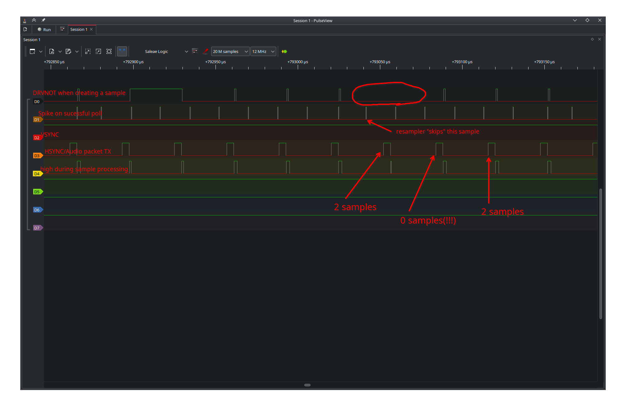
Not sure if that is spec-violating amounts of TX jitter...
Also, this is actually with increased poll rate, which doesn't seem to make a difference to this, but for completeness, to get that, change the code below
.serloopto.serloop sub scantimecomp,#4 + (3*4) call scanfunc call audio_poll_func call scanfunc@rogloh here is an amazing branch with a special case that prevents lines with zero samples: https://github.com/IRQsome/neoyume/tree/jitter-reduction-hack-test-shizzle
**Y O U F I X E D I T ** ! ! ! !
It's working now on my Plasma TV! A pure solid tone. Happy Days. That was the issue. It doesn't like zero sample packets which would obviously create jitter. This is awesome.
I'm gonna try it on my AVR but I think it will work there too.
Awesome!
I think if works on @rogloh plasma will work everywhere..
Yeah and it also now works on my Marantz AVR too.") A pure solid tone was just heard on that now.
A pure solid tone was just heard on that now.
Don't celebrate early, it has to work in the actual application, too.") Solid test tone is a good step though. Also need to think about how I'm going to refactor all these hacks into something nice
Solid test tone is a good step though. Also need to think about how I'm going to refactor all these hacks into something nice
I have faith in you !!!
So does it work playing actual games?
Gloriously.
The one word we needed to hear
For those of us playing along at home, this has been a great thread! Congrats! To paraphrase Capt. Mal, You've done the impossible and that makes you mighty!
Could someone please do a brief summary of why HDMI audio was not working and why it is now, in fairly simple terms?
EDIT:
Or how to guarantee HDMI audio works.
Do note that it always did work on mostTM hardware (sample sizes here in the single digits)
Very briefly:
Apparently not needed:
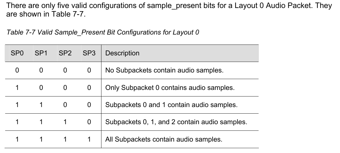
Thanks. I don't have the HDMI Eval board so I haven't tried DVI/HMDI yet. What is a "zero sample packet"?
An audio packet that contains 0 samples. Each packet can have between 0 and 4 samples inside. Explicitly pointed out as valid by the spec:
(Though part of me wants to have the audio infoframe even if it's not strictly needed... hmm. It would be needed for experimenting with surround sound, but I don't have any sinks in the house that can really support it)
Agree the Audio infoframe didn't seem to be needed in my case and the channel status sample rate certainly has an effect on some devices.
Plus some devices need the 5V present to work as well, even sometimes just for the audio, while video could still get through without it as I discovered for my TV. That made it especially hard to get any HDMI audio working at all really, because when I tested without the 5V and it didn't work and adding it back didn't improve things at the time I didn't believe I needed it given video already worked, which set me back a bit until other problems got fixed first and I retried the 5V power again later. Conversely my AVR needed 5V for both video+audio to get through at all.
I have a 5.1 multichannel AVR setup that should do multi-channel if you ever wanted to test something on it.
I was thinking for multi-channel you could copy the L+R samples for up to 6 further channels (8 total channels) into the 3 additional neighbouring pins in 32 bit repo mode (making 8 total channels of 16 bit data on 4 smartpins) and the resampler could pack more samples in if there is sufficient encoding time per scan line. You may need higher resolution though for more island capacity and the P2 pixel rate is going to be limited to <35Mpixels/s. The base repo pin could be the trigger which is written to last by the audio generator COG(s) and reading it as full then causes the HDMI (resampling) driver to go read from all other other repo pins to get the other 6 channels of audio sample data.
EDIT: no I think 8 channel 48kHz would still be doable with two data packets per 31.5kHz scan line.
Yea, you only need three packets at most (two samples + regen). You also could kiss the resampler goodbye, not sure where you'd find any surround data that has a non-standard native sample rate (for any P2-original synth code, you'd just go with 32kHz...). In such a case it might also be useful to use a memory FIFO instead of mailbox pins (in which case the video driver is now responsible for driving the analog DACs)
EDIT: Also edited the 5V info into the previous post
My tests are with 5v connected directly to the rail. Never had a problem with that.
You could potentially experience strange back-powering effects or even destroy the P2 pins if they get shorted to the 5V rail. Resistor is just safer.
It's just there to feed power into the EDID chip and to detect a device plugged in during HPD event etc so you could wire it direct if your 5V is stable. Even so it might be safer/nicer to (poly)fuse it though or a small resistor could at least limit current in either condition in case of some sort of overvoltage or other fault rather than fry the P2 regs or the HDMI device. I'm actually using 3.3V instead of 5V to be a little safer near P2 IO pins and it still works as well for me.