TAQOZ Reloaded v2.8 - SI5351 dual RF signal source control

This code controls the frequency of the two independent channels of an SI5351 chip over the range 8kHz to 120MHz.
N.B. Two constants may need altering:-
fref needs changing to the clock frequency driving your SI5351
vfoadr may need changing to the address of your SI5351, as reported by the Taqoz startup message
The commands are as follows:-
RFinit ( -- ) Initialise the SI5351 ready for use. Turns output pins CLK0 and CLK1 off ( no output pulses )
CLK0 ( -- ) Select the output from pin CLK0 as the currently selected channel - all commands will go to that channel until the other channel is selected
CLK1 ( -- ) Select the output from pin CLK1 as the currently selected channel - all commands will go to that channel until the other channel is selected
RFtune ( frequency -- ) Set the currently selected channel to 'frequency' Hz. This has been tested over the frequency range 8000 to 120000000 Hz
RFon ( -- ) Turn the currently selected channel on, approx 3.3V high pulses will appear at the output
RFoff ( -- ) Turn the currently selected channel off
There are some test words at the bottom to check the data being created and read the SI5351 settings. During development, the application note AN619 from SI was useful, as was this website. Referring to the SI5351 diagram on the latter website, my code holds three of the frequency setting parameters constant - e=0, f=1 and c = 1048575, to simplify the maths. The value of c is the largest permitted and this allows b to vary over the widest range and thus give the smallest tuning resolution. The OMD division ratio is maintained as an even integer which is said to minimise clock jitter. All these simplifications are to improve tuning speed, when controlled by a rotary encoder, so as to sound as smooth as possible - radio enthusiasts spend a lot of time hunting for weak signals, so any notchy tuning artifact would be unwelcome. I've swept the output in frequency and listened to it with a receiver and it sounds like an analogue oscillator, which is great. Measurement of the SWEEP word showed that RFtune took an average of 245uS @ 200MHz P2 clock. That equates to being able to update frequency ~4000 times/s! The precision of the maths means the actual frequency is within about 2Hz of the demanded frequency, so be aware of that.
Only if used in a radio application, for best purity of the signal generated, I've read it's best to use just one channel per SI5351 as the cross talk between channels increases clock jitter slightly. For other applications, it's usually not an issue.
Here's the code:-
TAQOZ

--- SI5351 DRIVER version 1 for TAQOZ Reloaded v2.8 by Bob Edwards G4BBY May 2021
--- Optimised for radio tuning by minimising the number of bytes sent to the SI5351
--- when a tuning step is demanded
--- N.B. In the CONSTANTS section, you need to check vfoadr matches your si5351 i2c address
--- and fref is the frequency clocking your si5351 - mine was quite a way out from the nominal 25MHz


IFDEF *SI5351*
    FORGET *SI5351*
}
pub *SI5351* ." SI5351 dual channel RF oscillator driver ver 1" ;

ALIAS I2C.START <I2C                        --- Matches the stop alias, I2C>
pri @. @ . ;                                --- Used quite a lot for debug display


--- CREATE and DOES> so we can define a new RECORD type

pub CREATE  ( -- )
    [C] GRAB
    [C] CREATE:                             --- Using the next word in the input stream as the name, create a VARIABLE type dictionary entry
    [C] GRAB                                --- make sure CREATE: has run before anything more
    HERE 2- 0 REG W!                        --- save the address of the code after DOES> in the REG scratchpad area
;

pub DOES>   ( -- )
    R>                                      --- the first word location in the new word being defined
    0 REG W@                --- retrieve the address stored on scratchpad
    W!                      --- set the first word to execute as the address of the code after DOES>
;

--- Record types

--- start a record definition, leave zero offset into the record tos
0   :=  [FIELDS     ( 0 -- )

--- define a new field within a record
pre FIELD
    CREATE OVER [C] || +    ( offset1 datasize -- offset2 )
    DOES> R> W@ +           ( recaddr -- recaddr+offset )
    ;

--- finalise a record definition4 FIELD BAB
ALIAS := FIELDS]


--- define a record array type
pre RECORDS ( fielddef recordnumber <arrayname> -- ; arrayindex -- adr )
    GRAB
    CREATE                                  --- in the dictionary entry...
        org@ [C] ||                         --- save start address of data
        OVER [C] ||                         --- and save the record size in bytes
        * [C] res                           --- then in the dataspace allot reqd no. of bytes
    DOES>
        R> DUP >R W@                        --- read the start address of the data
        R> 2+ W@                            --- read the record size in bytes
        ROT * +                             --- and compute the start address of the reqd record
;

private
--- constants
$C0         := vfoadr                       --- SI5351 i2c address
25008325    := fref                         --- nominal crystal frequency driving the si5351
750000000   := pllmid                       --- PLL frequency midrange
600000000   := pllmin                       --- PLL minimum permitted frequency
900000000   := pllmax                       --- PLL maximum permitted frequency
1048575     := C                            --- FMD parameter C is maintained as a constant

--- variables
long frequency                              --- required o/p frequency for the active channel
long Rfreq                                  --- reqd OMD o/p frequency, before R divider
long pllfreq                                --- reqd pll frequency
long A                                      --- A parameter of the FMD divider
long B                                      --- B parameter of the FMD divider
byte R                                      --- The R divider parameter
byte LASTREG                                --- address of SI5351 register last written to in autoincrement mode
byte pllreset                               --- pllreset set 1 if pll reset needed
byte RFactive                               --- set to 0 or 1 to select CLK0 or CLK1 as active channel for cmds
long @1                                     --- scratch register 1
long @2                                     --- scratch register 2
public

---  scratch register access
pri 1@ @1 @ ;
pri 2@ @2 @ ;
pri 1! @1 ! ;
pri 2! @2 ! ;


--- Storage definition for one RF channel - remember word and long boundaries
--- the size of the record has to be maintained a multiple of 4, so all records will be aligned
--- This can be achieved by an extra dummy entry if need be
--- NB keep .msx_p1, .msna_p2 and .msna_p1 in this order and together
--- This ordering is relied on to speed up register transmission to the SI5351

[FIELDS
    4 FIELD .frequency      --- output frequency
    4 FIELD .OMD            --- OMD
    4 FIELD .msx_p1         --- OMD intermediate value + rx_div + msx_divby4
    4 FIELD .msna_p2        --- FMD intermediate value
    4 FIELD .msna_p1        --- FMD intermediate value
FIELDS] RFparam


--- Create a 3 record array for the two independent RF sources + another record as scratchpad

org@ 4 ALIGN org                        --- Ensure array starts on a long boundary
RFparam 3 RECORDS RFparams              --- record 0 = CLK0 params, record 1 = CLK1 params
                                        --- record 3 = copy of last params of active channel
                                        --- to allow SI5351 register changes to be detected

--- CLK0, CLK1 are used to select the active channel to be worked on, this state stored in variable RFactive

pri RFparams@ RFactive C@ RFparams ;    ( -- adr ) --- start adr of active channel params
pri RFoldparams@ 2 RFparams ;           ( -- adr ) --- start adr of params from last cycle
pub CLK0 0 RFactive C! ;                ( -- ) --- select CLK0 as the active channel
pub CLK1 1 RFactive C! ;                ( -- ) --- select CLK1 as the active channel

--- Calculation of SI5351 register values

--- from the new output frequency and old OMD setting - the latter is allowed to be any number on start up
--- calculate the new OMD as d + e=0 / f=1, which is just d, and new pll frequency required

--- calculate R divider and equivalent o/p frequency
pri RCALC   ( freq1 -- R freq2 )
    DUP 500000 <
    IF
      2                         --- R = 2 seed value
      7 0 DO
            2DUP * 500000 >     --- check if freq1 * R > 500kHz
            IF
                LEAVE           --- yes, f now > 500kHz,so leave loop
            ELSE
                2*              --- no, then set R = R * 2
            THEN
        LOOP                    --- and try again
        SWAP 2DUP * SWAP DROP
    ELSE
        1 SWAP                  --- R is 1 for frequencies over 500000, freq2 is no change
    THEN
;

--- calculate the new Output Multisynth Divider, flg=1 if pll reset reqd.
pri OMD     ( freq oldOMD -- newOMD pllfreq flg )
    2DUP *
    DUP pllmin pllmax WITHIN
    IF                  ( freq oldOMD pllfreq )
        ROT DROP 0
    ELSE                ( freq oldOMD pllfreq )
        DROP DROP DUP   ( freq freq )
        pllmid SWAP /   ( freq newOMD )
        DUP 1 AND
        IF
            1+
        THEN            ( freq newOMD' )
        SWAP OVER * 1   ( newOMD pllfreq )
    THEN
;


--- calculate a,b for parameters  a + b / c for the Feedback Multisynth Divider from the pll frequency
--- C is a constant, $FFFFF, the largest value permitted, so that widest b range gives best frequency precision
pri FMD                 ( pllfreq -- a b )
    DUP fref / SWAP         ( -- a pllfreq )
    C fref */               ( -- a c*pllfreq/Fref )
    OVER C * -              ( -- a b )
    ;                       ( -- a b )

--- The SI5351 requires the above parameters to be packed in the following way...

--- calculate msna_p1
pri msna_p1!
    A @ 7 <<        --- A*128
    B @ 7 <<
    C /             --- 128*B/C
    +
    512 -
    RFparams@ .msna_p1 !
    ;

--- calculate msna_p2
pri msna_p2!
    B @ 7 << DUP                --- 128*B
    C /                         --- (128*B)/C
    C *                         --- C*((128*B)/C)
    -
    $F00000 +                   --- Set top four bits of msna_p3, which is a constant $FFFFF
    RFparams@ .msna_p2 !        --- 128*B-C*((128*B)/C)
    ;


--- calculate msx_p1, complete with msx_divby4 and rx_div bit fields
pri msx_p1!     ( -- )
    RFparams@ >R
    R> DUP >R .OMD @
    128 * 512 -
    Rfreq @ 150000000 >
        IF
            $0C0000 +           --- MS0_DIVBY4
        THEN
    R C@ DUP 1 =
        IF
            DROP 0
        ELSE


  | 20 <<            --- R0_DIV


        THEN
    +
    R> .msx_p1 !
    ;

--- Copy the active channel params record to the scratchpad record
pri OLDPARAM!   ( -- )
    RFparams@ RFoldparams@ RFparam CMOVE
    ;

--- calculate and store all parameters in the currently selected channel record
pri PARAM!  ( frequency -- )
    RFparams@ >R
    DUP frequency !         --- o/p frequency in active channel record
    RCALC SWAP
    R C!                        --- save the R divider parameter
    DUP
    Rfreq !                     --- save the OMD divider o/p frequency
    R> DUP >R .OMD @
    OMD
    pllreset C!                 --- save pllreset - 1 = reset needed
    DUP pllfreq !               --- save pllfreq
    FMD
    B !                         --- save A
    A !                         --- save B
    R> .OMD !                   --- save OMD
    msna_p1!                    --- calculate msna_p1
    msna_p2!                    --- calculate msna_p2
    msx_p1!                     --- calculate msx_p1
;

--- SI5351 I2C words

--- Read byte at register adr in si5351
pri VFOC@ ( adr -- byte )
    <I2C vfoadr I2C! I2C!                   --- select the register at 'addr'
    <I2C vfoadr 1+ I2C! nakI2C@ I2C>        --- read the contents
    ;

--- Write byte to register adr in si5351
pri VFOC! ( byte adr -- )
    <I2C vfoadr I2C! I2C! I2C! I2C>
    ;

--- Write a byte to SI5351 register using autoincrement address where possible
pri INCVFOC! ( byte adr -- )
DUP LASTREG C@ 1+ =                         --- is this register = last register +1?
    IF
        DROP
        I2C!                                --- yes, just send the register value
    ELSE
        <I2C vfoadr I2C! I2C! I2C!          --- no, set up the register address and then send value
    THEN
;


--- part of sendFMD and sendOMD
pri sendbytes   ( ptr_to_data -- )
3 FOR                                       --- Do for all 3 bytes, decrementing new byte pointer
    DUP I - C@ 1@ C@ <>                     --- Are the new and old byte values different?
        IF
            DUP I -  C@ 2@ INCVFOC!         --- Yes, so send the new byte to the SI5351 register
            2@ LASTREG C!                   --- Save reg address to check for autoincrement
        THEN
    @1 --                                   --- Point to next lowest old byte
    @2 ++                                   --- Increment register address
NEXT
DROP
;


--- Send FMD to the SI5351 - all bytes if 1st time, else only changed bytes
pri sendFMD ( -- )
    RFactive C@
    IF 36 ELSE 28 THEN 2!                   --- register start address, depends on active channel selected, store in memory 2
    RFoldparams@ .msna_p1 2 + 1!            --- memory 1 = pointer to MS byte of old .msna_p1
    RFparams@ .msna_p1 2 +                  --- pointer to MS byte of .msna_p1
    sendbytes
    RFoldparams@ .msna_p2 2 + 1!            --- memory 1 = pointer to MS byte of old .msna_p1
    RFparams@ .msna_p2 2 +                  --- pointer to MS byte of .msna_p2
    sendbytes
;

--- Send OMD to the SI5351 - all bytes if 1st time, else only changed bytes
pri sendOMD ( -- )
    RFactive C@
    IF 52 ELSE 44 THEN 2!                   --- register start address, depends on active channel selected, store in memory 2
    RFoldparams@ .msx_p1 2 + 1!             --- memory 1 = pointer to bottom of previous params, MS byte of old .msx_p1
    RFparams@ .msx_p1 2 +                   --- point to MS byte of new .msx_p1
    sendbytes
;

--- Wait until si5351 initialisation complete
pri VFOINIT?    ( -- )
    BEGIN
        0 VFOC@
        $80 AND 0=
    UNTIL
    ;

--- Disable all clock outputs
pri VFO_OPS_DIS ( -- )
    $FC 3 VFOC! ;

--- Power down all clocks using register 16-23
pri VFOCLKSOFF  ( -- )
    8 FOR
            $80 I 16 + VFOC!
    NEXT
;

--- Set crystal as both PLL source
pri VFOXTAL ( -- )
    0 15 VFOC!
    ;

--- Set all disabled outputs low
pri VFOOUTLOW   ( -- )
    0 24 VFOC!
    ;

--- Init Multisynth constants
pri VFOSYNTHINIT    ( -- )
    $FF 26 VFOC!
    $FF 27 VFOC!
    $FF 34 VFOC!
    $FF 35 VFOC!
    0 42 VFOC!
    1 43 VFOC!
    0 47 VFOC!
    0 48 VFOC!
    0 49 VFOC!
    0 50 VFOC!
    1 51 VFOC!
    0 55 VFOC!
    0 56 VFOC!
    0 57 VFOC!
    ;

--- Power up CLK, PLL, MS for currently selected channel
pri VFOPLLON    ( -- )
    RFactive C@
    IF
        $4F 16
    ELSE
        $6F 17
    THEN
    VFOC!
    ;

--- Reference load setup
pri VFOREFSET   ( -- )
    $12 183 VFOC!
    ;


--- CLK output enable  for currently selected channel
pub RFon    ( -- )
3 VFOC@
RFactive C@
IF
    $FD
ELSE
    $FE
THEN
AND 3 VFOC!
;

pub RFoff   ( -- )
3 VFOC@
RFactive C@
IF
    $02
ELSE
    $01
THEN
OR 3 VFOC!
;

--- reset the PLL on the currently active channel
pri RESETPLL    ( -- )
RFactive C@
    IF
        $80
    ELSE
        $20
    THEN
    177 VFOC!
;

--- Initialise the SI5351 ready for frequency setting
pub RFinit      ( -- )
    VFOINIT?                                --- wait until si5351 has initialised
    VFO_OPS_DIS                             --- disable both outputs
    VFOCLKSOFF                              --- power down all clocks
    VFOXTAL                                 --- set crystal as PLL source
    VFOOUTLOW                               --- set all disabled O/Ps low
    VFOSYNTHINIT                            --- initialise multisynth constants
    VFOREFSET                               --- Reference load start up
    RFactive C@
    2 0 DO
          I RFactive C!
          VFOPLLON                          --- power up CLK, PLL, MS0
          RFoff                             --- but set both o/ps off for now
        LOOP
    RFactive C!
;

--- set the si5351 current channel to frequency
pub RFtune      ( frequency -- )
      0 LASTREG C!                          --- Ensure we get a proper I2C address setting start
      OLDPARAM!
      PARAM!                                --- calculate register values
      sendOMD                               --- send the OMD registers to the SI5351
      sendFMD                               --- send the FMD registers to the SI5351
      I2C>                                  --- end the i2C transfer
      pllreset C@
      IF
        RESETPLL
      THEN                                  --- reset the pll
;

--- Test Words

--- display all params for the selected channel
pub RFparam.        ( -- )
CRLF CRLF ." RFparams settings..."
RFparams@
CRLF ."  frequency = " frequency @.
CRLF ."          R = " R C@ .
CRLF ."      Rfreq = " Rfreq @.
CRLF ."        OMD = " DUP .OMD @.
CRLF ."    pllfreq = " pllfreq @.
CRLF ."          A = " A @.
CRLF ."          B = " B @.
CRLF ."          C = " C .
CRLF ."    msna_p1 = " DUP .msna_p1 @.
CRLF ."    msna_p2 = " DUP .msna_p2 @.
CRLF ."    msna_p3 = " $FFFFF .
CRLF ."     msx_p1 = " DUP .msx_p1 @.
CRLF ."   pllreset = " pllreset C@ .
CRLF
;


--- Display ONE si5351 register
pub VFOREG. ( adr -- )
    TAB ." Register "
    DUP DEC . TAB ." : "                    --- display register address
    DUP VFOC@                               --- read the register
    DUP . ." decimal " TAB                  --- and display it in decimal
    .BYTE ."  hex " TAB                     --- also in hex
    DROP CRLF                               --- Taqoz needs CRLF rather than the CR in Tachyon
    DEC
;

pri .RES TAB ." Reserved" CRLF ;

--- Display all si5351 registers
pub VFOREGS. ( -- )
    CRLF CRLF
    TAB ." si5351 REGISTER READOUT"
    CRLF CR
    4 FOR I VFOREG. NEXT
    .RES
    9 VFOREG.
    .RES
    13 FOR I 15 + VFOREG. NEXT .RES
    7 FOR I 29 + VFOREG. NEXT .RES
    134 FOR I 37 + VFOREG. NEXT .RES
    177 VFOREG. .RES
    183 VFOREG. .RES
    187 VFOREG.
;

--- This checks that the params were calculated correctly by back-calculating the output frequency
pub FREQCHECK.  ( -- )
      RFparams@ >R
      fref A @ *                            --- fref * A
      fref B @ C */                         --- fref * B / C
      +
      R C@ /
      R> .OMD @ /
      CRLF CRLF
      ." The si5351 params will give an output of " . ." Hz" CRLF
;

--- Display the PLL lock status - PLL locked if healthy
pub LOCK.
0 VFOC@
CRLF  ." Channel A pll "
DUP $20 AND IF ." unlocked" ELSE ." locked" THEN
CRLF  ." Channel B pll "
$40 AND IF ." unlocked" ELSE ." locked" THEN
CRLF
;

--- Tune from start to stop frequency, stepping 10Hz as fast as possible, stop if key pressed
pub SWEEP   ( startfreq stopfreq -- )
RFinit >R
RFon
BEGIN                                       --- save the stop frequency on the R stack
    DUP RFtune
    10 +
    DUP R> DUP >R => KEY 0<> OR
UNTIL
DROP
R> DROP                                     --- clear the R and data stacks
;

pub SWEEPtest
3600000 3800000 SWEEP
;

END
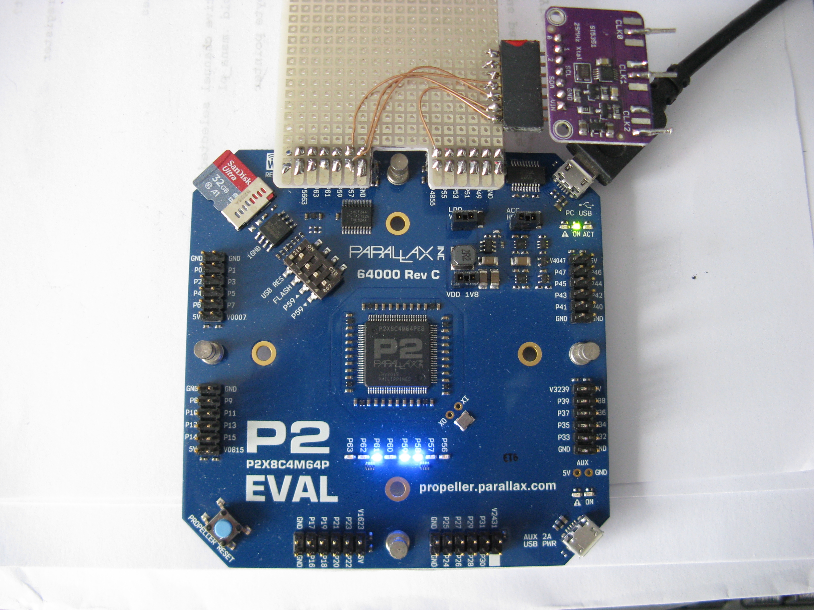
Here's my lash up of an adapter to connect the SI5351 breakout board to the P2 on the default I2C pins.