

Playing with the Parallax P2 Panel64
 iseries
Posts: 1,547
iseries
Posts: 1,547
I was waiting for these panels to come into stock before I started investigating them.
When it became available I order one and started looking into how I would hook this up to my P2 Edge board. The description at the bottom said complete specifications were available under the download tab.
Well there seems to be no mention any where I could find that tells me the size of the connector used to plug into the socket. I could guess but then I could be wrong. Well it turns out to be just a .1 inch connector with 16 pins. This made it simple to build a plug.
When I got the panel it was smaller than I had imaged and was a good size for up close viewing. It was a little scary as the LED's are just mounted on the front of the panel just spaced out. You can feel them with your finger leading me to trying not to bump this side and nock one of those LED's off the board.
The power supply cable was way beefier than I thought was needed but that's what it came with. I purchased the 3 amp power supply with the unit and I planed on using the power cable for the P2 to drive this board. So I soldered on a barrel connector and was good to go.
Next was the 16 wires I needed to look into. The complete specification did nothing to show the pinout of this connector. I looked around on the internet and there seems to be one image that is used by a number of different sites. I used a continuity meter to see where the ground pins where to validate that the pins where in the correct order.
Now I could have used the flat cable it came with and plug in each wire to that but thought how am I going to remember what pin goes to what pin on the P2. I thought that maybe it would be better just to solder up two cables and layout the pins the way I wanted to so that I could just map them later in the software. Here is a picture of my final setup: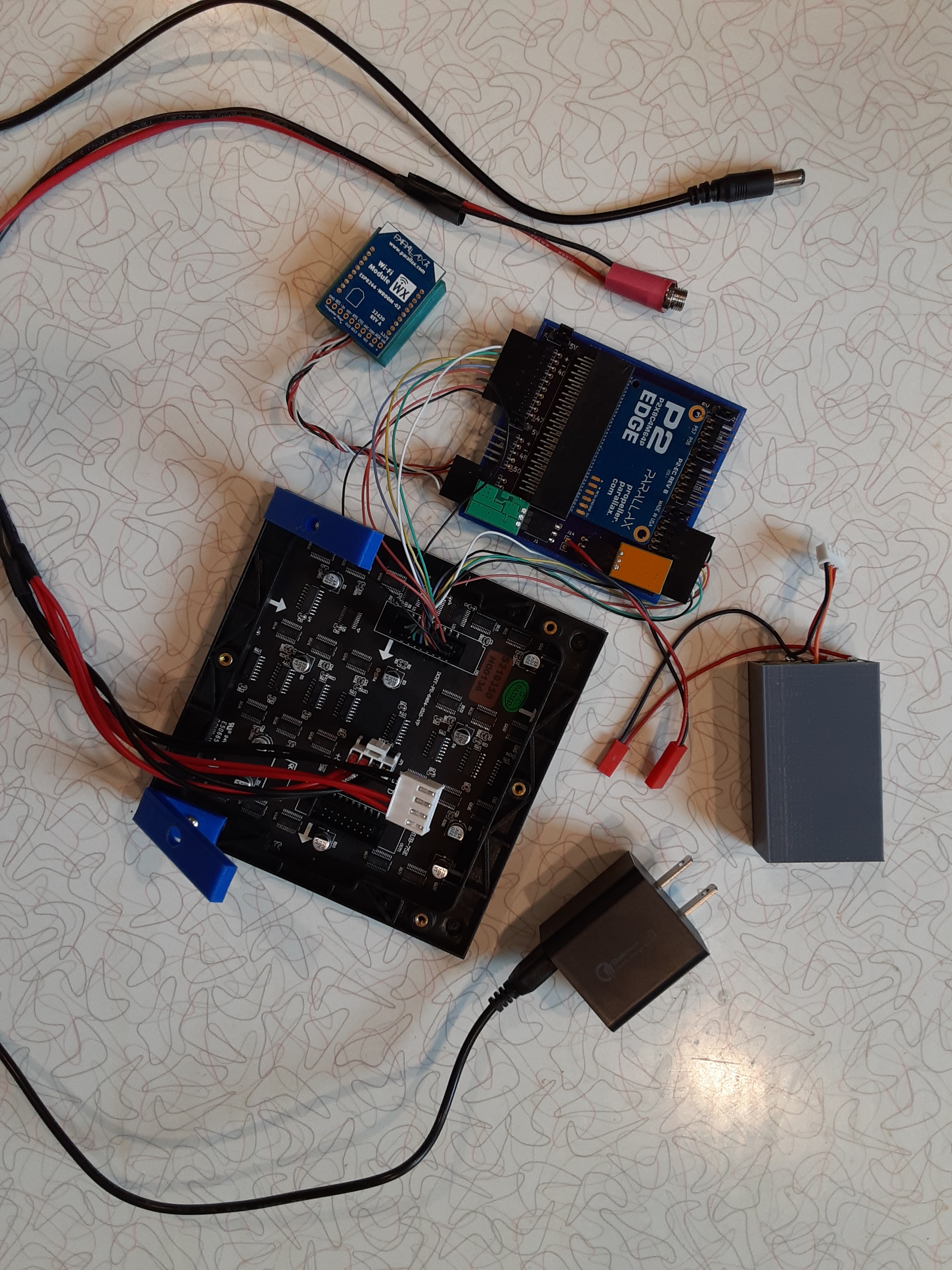
Oh, one more thing is I went ahead and printed some feet so that it will sit at a 45 degree angle for easy viewing.
Now my first goal was to turn on one LED to some color. This took several tries with no luck. The display would just flash one line of LED's and that was it. From the documentation that I found is that if OE is held low that row of LED's would be turned on. Well they turn on but then they turn back off. I guess this is a feature so that if the display driver goes down that the screen doesn't burn it a row of LED's that were last accessed by the driver.
There was also talk about using level shifters to go from the 3.3v of the P2 to 5v of the panel. I have seen many post on that and most say it should work fine without the level shifters.
After several attempts at coding something up I finally got the order of instructions down. For a while there the row was updating after I updated the row data.
The order I'm using is I clock the data in 64 bits total and then I set the address and latch it. Finally I lower the OE pin for a few microseconds and then raise OE. This is done for each of the 32 rows where the first and 32 rows are output at the same time.
So my original goal of one LED turned out to be it was easier to just output a whole row of data with one color. By running the code for all rows I was able to output one color on the top 32 rows and one color on the bottom 32 rows. Now the refresh rate controls how bright the display is so I think I have a good time set to display the data without burning the image into my eyes.
Now I merged the display with some graphics routines I used with some other display in the hope of displaying something useful on the panel instead of some solid colors. This worked out rather nicely and here is a picture of the results: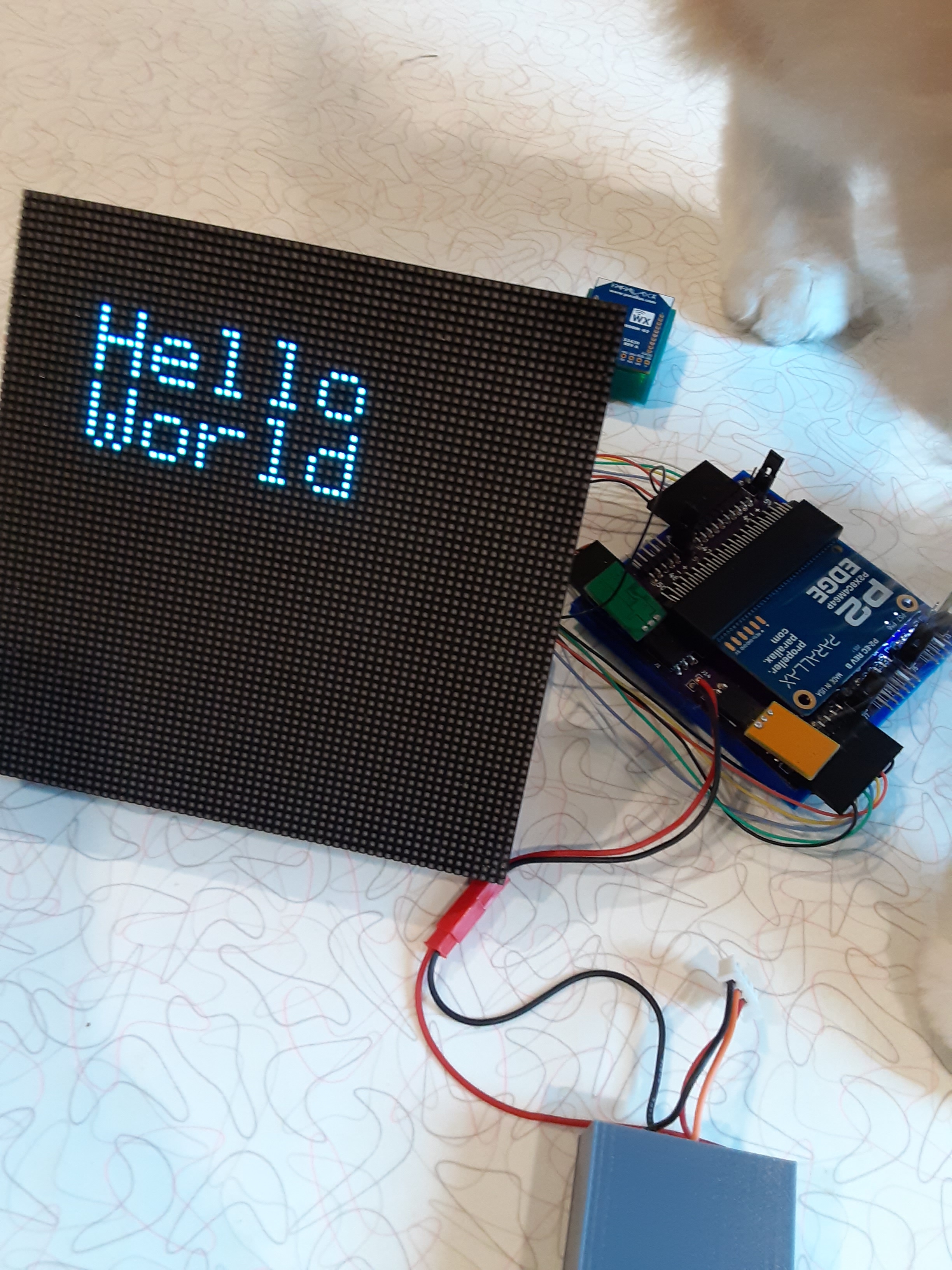
This is the code used to produce that image:
#include <stdio.h>
#include <propeller.h>
#include "Panel64.h"


int main(int argc, char** argv)
{
    int c;

    Panel_Start();

    c = Panel_Color(1, 1, 0);

    Panel_TextColor(c, 0);
    Panel_WriteSStr(10,10, "Hello");
    Panel_WriteSStr(10,18, "World");

    while (1)
    {
        _waitms(1000);
    }
}
The Panel64 library I will be putting up on my Github page.
This is the code to do the refresh of the panel:
    //setup pins
    _dirh(PNA);
    _dirh(PNB);
    _dirh(PNC);
    _dirh(PND);
    _dirh(PNE);
    _dirh(PNR1);
    _dirh(PNG1);
    _dirh(PNB1);
    _dirh(PNR2);
    _dirh(PNG2);
    _dirh(PNB2);
    _dirh(PNCLK);
    _dirh(PNOE);
    _dirh(PNLAT);
    _pinh(PNOE);
    _pinh(PNLAT);
    _pinl(PNCLK);

    while (1)
    {
        for (int i=0;i<32;i++)
        {
            for (int j=0;j<64;j++)
            {
                doColor(Buffer[j][i], Buffer[j][i+32]);
                _pinh(PNCLK);
                _pinl(PNCLK);
            }
            doAddress(i);
            _pinh(PNLAT);
            _pinl(PNLAT);
            _pinl(PNOE);
            usleep(20);
            _pinh(PNOE);
        }
    }
}
The code is not all that complicated as I had first thought. When trying to figure out all those pins and getting them to work looked at first to be a daunting task. So from start to finish I guess it took me about a day to pull it all together. It took some time to solder all those wires and put them in the plugs.
Now I need to finish up my panel driver.
Mike