Multi port serial input to P2
 DiverBob
Posts: 1,125
I've been converting P1 code to P2 for my 6 legged robot. I have some test code I am using to check out the RGB lighting and multi-port communications that is coming in from 6 independent P1 controllers into the Cluso99 multi-port serial. The RGB setup is working great, no issues there. But the serial data from the P1's is not working correctly.
The first image shows the debug output as the P2 queries each individual P1 controller. The correct format consists of: "$,nnn,n,n,vvv,v,v,ccc,c,c,x". Leg 3 and 6 seem most error prone on the output and it is consistent.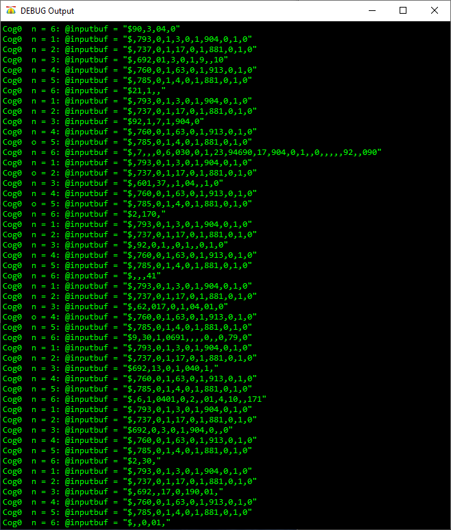
Output to PST shows basically the same output as the Debug window.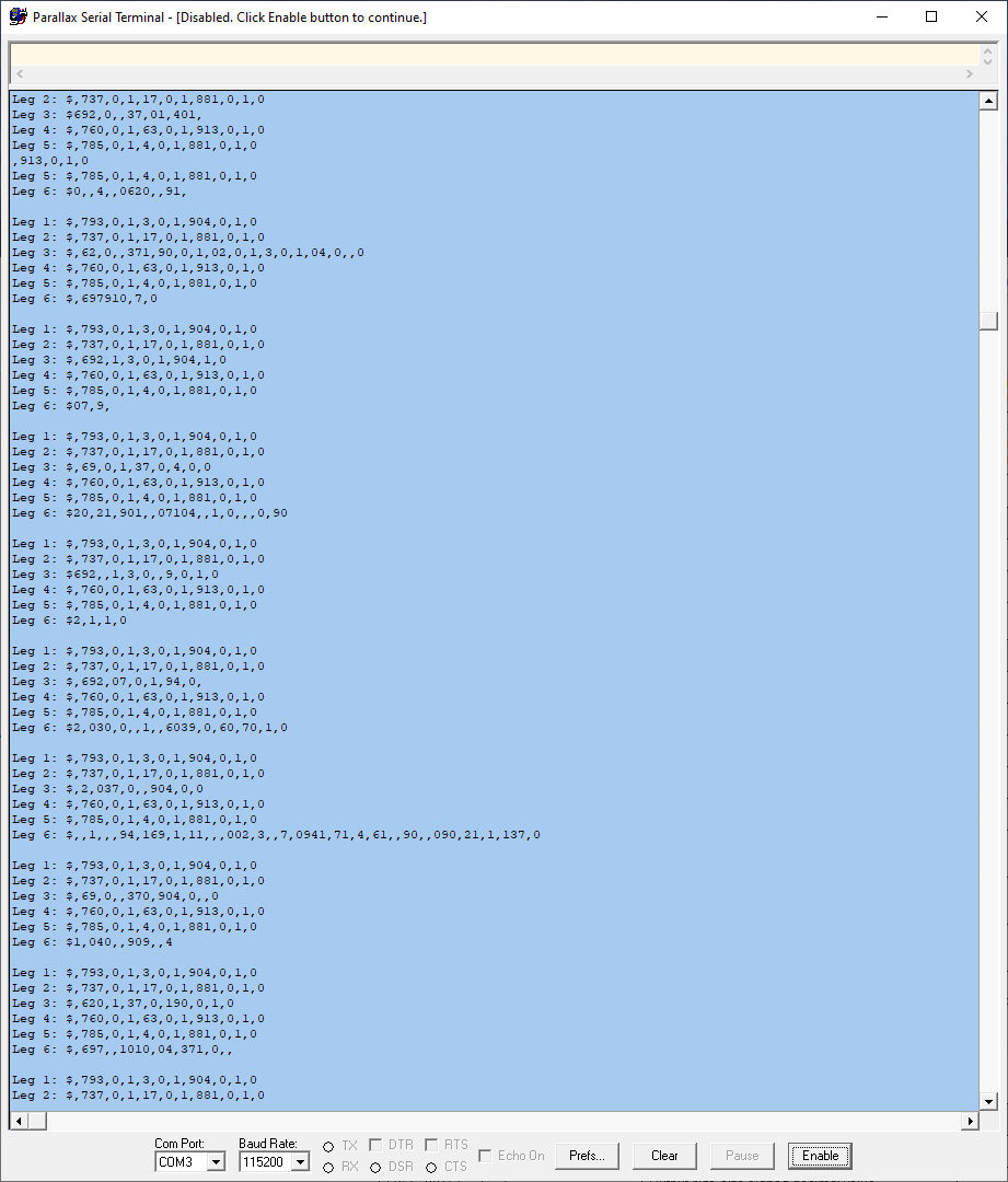
Next step was checking each individual P1 output using a logic analyzer to validate the output data was coming into the P2 correctly. This snapshot shows the basic timing of the 6 inputs, the top line is leg 1 and is in order (leg 2 is line 2, etc)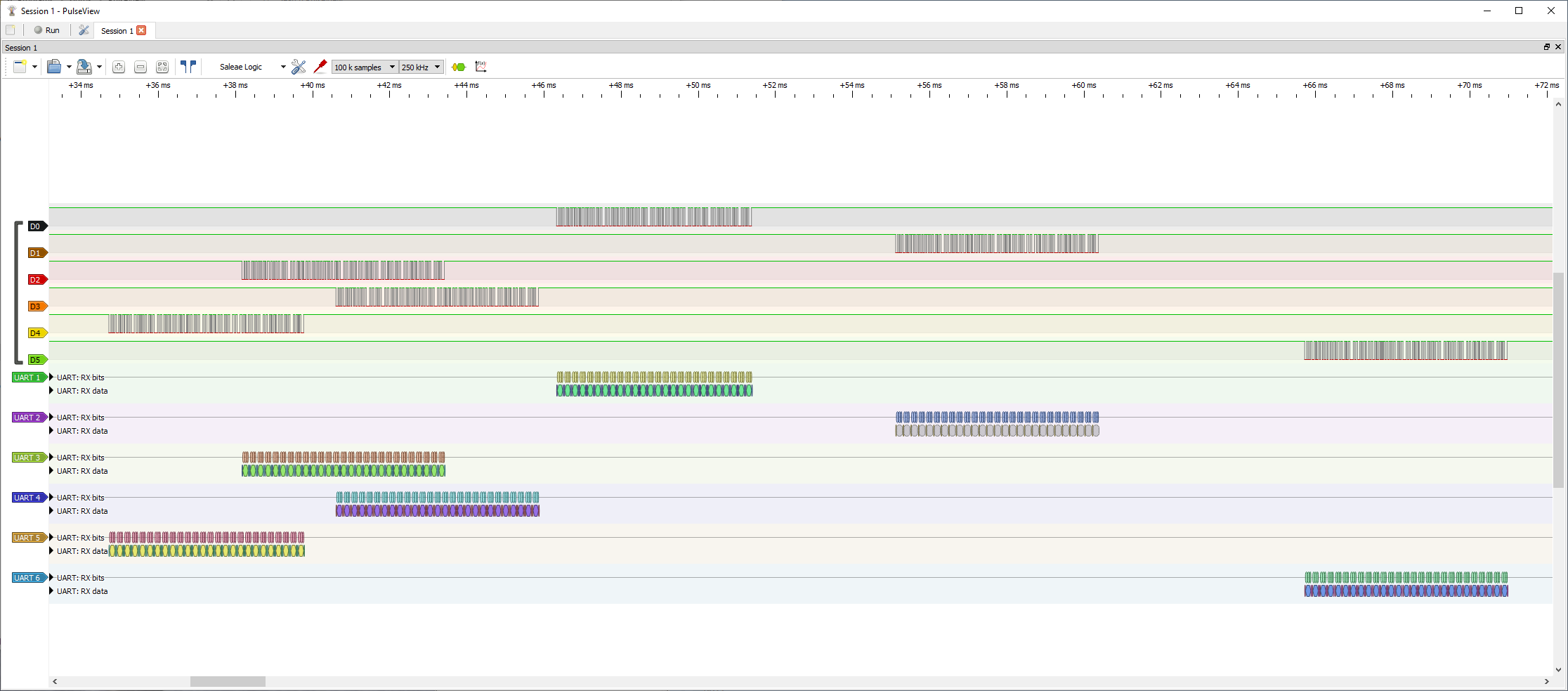
Leg 3 and 6 are the most error prone values. This snapshot shows the correct ansii output being produced by the P1 controller. So the data coming into the P2 is correct but it isn't being read correctly.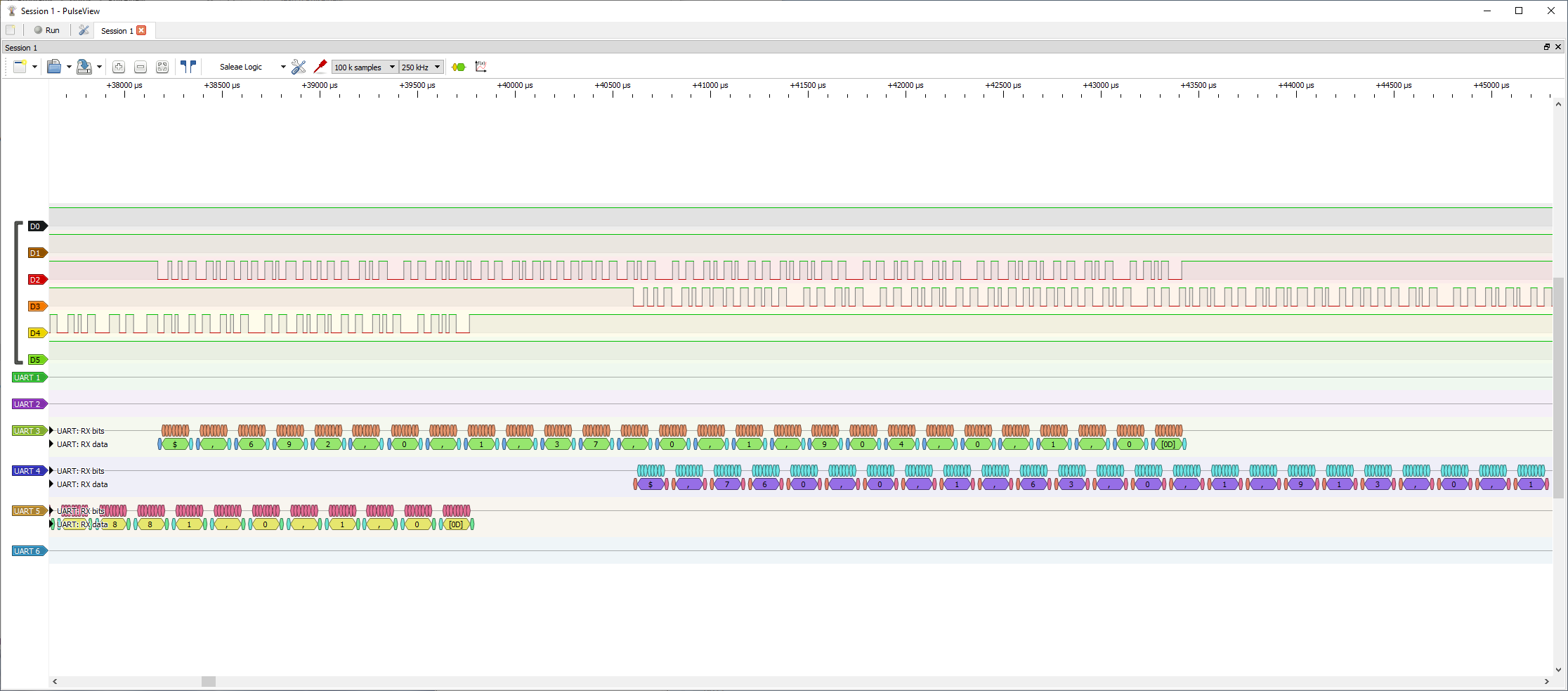
This is the Leg 6 P1 output
This leads me to believe my issue lies either in the way I set up the ports or the p1 to P2 conversion of the Getcmd1() code. I attached an archive of the test code, hopefully someone can see where I'm making my mistake(s).


Comments
I notice with the debug output, following the Cog0 message, the n is occasionally output as o. This is $6e vs $6f IIRC. This could be indicative of some bit timing slippage???
I thought that too but couldn't replicate that issue using Debug today. So I decided to start with basic troubleshooting and try to eliminate potential causes.
I started by first validating all 6 P1 controllers were outputting valid strings per the logic analyzer, got good continuous outputs from each controller. Did not detect any errors in any of the output strings.
Next step was switching over to the PST terminal and verifying it was giving the same basic outputs with the L3 and L6 data typically bad. PST had the same errors detected and shown in my previous posting. I also checked Debug with the same results as shown using PST.
I swapped the L2 -> L3 and L5 -> L6 with no change in the L3 and L6 values to eliminate the possibility of a wiring issue. Since the output errors didn't change, it appears to be problem with the L3 and L6 RX ports.
I also noticed that the PST output now stops dead after displaying around 3155 characters, didn't notice it doing that yesterday and not sure why I'm seeing that today.
I further simplified the code to try to eliminate any other factors so the testports() looks like this now (full code archived below):
pub testports() | chr, n

  ser.txChr(ser.CLS)
  ser.fstr0(string("Output feedback values...\r\n"))
  repeat
    'get feedback string into buffers - separate buffers due to data dropout
    ser.txChr(ser.CR)
    repeat n from 1 to 6
      'retrieve leg feedback string data from individual leg controllers
      case n
        1: wordfill(@LegBuffer1, 0, 128)                    'clear buffer
           serL1.rxstr(@LegBuffer1)
        2: wordfill(@LegBuffer2, 0, 128)                    'clear buffer
           serL2.rxstr(@LegBuffer2)
        3: wordfill(@LegBuffer3, 0, 128)                    'clear buffer
           serL3.rxstr(@LegBuffer3)
        4: wordfill(@LegBuffer4, 0, 128)                    'clear buffer
           serL4.rxstr(@LegBuffer4)
        5: wordfill(@LegBuffer5, 0, 128)                    'clear buffer
           serL5.rxstr(@LegBuffer5)
        6: wordfill(@LegBuffer6, 0, 128)                    'clear buffer
           serL6.rxstr(@LegBuffer6)

    ser.fstr0(string("Leg1: "))
    ser.txStr(@legBuffer1)
    ser.txChr(ser.CR)
    ser.fstr0(string("Leg2: "))
    ser.txStr(@legBuffer2)
    ser.txChr(ser.CR)
    ser.fstr0(string("Leg3: "))
    ser.txStr(@legBuffer3)
    ser.txChr(ser.CR)
    ser.fstr0(string("Leg4: "))
    ser.txStr(@legBuffer4)
    ser.txChr(ser.CR)
    ser.fstr0(string("Leg5: "))
    ser.txStr(@legBuffer5)
    ser.txChr(ser.CR)
    ser.fstr0(string("Leg6: "))
    ser.txStr(@legBuffer6)
    ser.txChr(ser.CR)
I also sightly modified the mpx_fullduplexserial rxStr() command to specifically wait for the "$" start character.
PUB rxStr(stringptr) | addr, chr
' wait for an input string (0 terminated, <cr> stripped)
' added mod to use $ as string start char for testing

  addr := stringptr
  chr := rxtime(100)                                                  ' new for testing
  if chr == "$"                                                             ' new for testing
'    byte[addr++] := chr                                             ' new for testing
    repeat
        chr := rxtime(100)                                               ' waits for an input char - modified line to rxtime vs rx()
        if (chr == BKSP or chr == DEL)                            ' <bs> ? (doesn't work in command line terminal!)
          chr := BKSP                                             ' force <bs>
          addr--
          if addr < stringptr                                     ' <bs> and empty buffer?
            addr := stringptr                                     ' y: so back to start of buffer
          else
  '         if (noecho == 0) and (0 <= txport < MAX_PORTS)
              txChr(BKSP)                                         ' <bs>
              txOut(" ")                                          ' <space>
              txChr(BKSP)                                         ' <bs>
        else
            byte[addr++] := chr                                     ' store char
    while chr <> CR                                               ' <cr> ?
    txChr(LF)                                                     ' <lf>
    byte[--addr] := 0                                             ' store terminating 0 (replaces <cr>)
This resulted in the attached PST output snapshot. Now the L1, L2, L4, L5 outputs look great but L3 and L6 are totally missing.
It appears to be a possible issue in the multi-port setup is not bringing in the values as I can't find any issues anywhere else in the code. Not sure how to proceed at this point, comments/ideas are welcome!
Bob
I don't think it is a failure to service in the multiport driver, but just in case, try disabling the top 8 ports as follows...
main_loop       setq      #4-1                                  ' get port_control from hub (all 16 bytes)
                rdlong    control, ptra                         ' ...

.port0          mov       portnum, #0                           ' set port[0]
                mov       control, control              wz      ' all ports 0-3 inactive?
    if_nz       call      #proc_active                          ' n: go process
.port4          mov       portnum, #4                           ' set port[4]
                mov       control, control+1            wz      ' all ports 4-7 inactive?
    if_nz       call      #proc_active                          ' n: go process
{{
.port8          mov       portnum, #8                           ' set port[8]
                mov       control, control+2            wz      ' all ports 8-11 inactive?
    if_nz       call      #proc_active                          ' n: go process
.port12         mov       portnum, #12                          ' set port[12]
                mov       control, control+3            wz      ' all ports 12-15 inactive?
    if_nz       call      #proc_active                          ' n: go process
}}
                jmp       #main_loop                            ' all done
Other ideas...
Is the leg data you are receiving running full-speed at 57,600? If yes, then you will need a higher rate to get the debug data out.
PST is only a basic terminal. I've seen it drop characters and it has a shortish buffer. You could try using loadp2 with the -t option from the windoze command prompt.
What P2 board are you using? If it's a P2D2/RetroBlade2/your-own, are you using a real PropPlug or CP2102 cheapie? There are some restrictions/issues with the CP2102 that I've not fully determined yet.
Thanks for your response Ray! This program is running on a P2 Edge plugged into the mini breakout board. The P1 data is coming from 6 RoboPi boards and being output at 57,600 (that was kind of the fastest the old P1 master could handle reliably). Using the old P1 master with a similar multi-port software I never saw these kinds of data drop outs and thought the P2 shouldn’t have any issues. Even then I was using the PST without dropouts like this. Even the Debug window shows the same data drops. It looks like the receiver code has a buffer that fills up when it gets to L3, drops the data and resets somehow so the next 2 data strings come in OK when it fills up before L6. It’s just too consistent even after stripping the code down to just the bare bones.
Actually, let me try running just L3 and L6 without the other receivers and see what happens.
I tested where I only output from the L3 and then the L6 port (all ports are still running but only receiving from one port at a time), same results with no data or garbage (mostly no data). I used the Debug command window to display the data (Not sure how to use loadP2 using the Prop Tool).
I also ran the L1, L2, L4 and L5 inputs one at a time using the Debug window. They all worked correctly other than the data locking up after a few hundred lines displayed.
In both the L3 and L6, running only one at a time there is mostly blank outputs and the lines with data is mostly garbage. Like the other inputs the data flow stops output after a few hundred lines, like the receiver code just locks up.
Ray, I commented out the lines you indicated and ran all the tests again with the same results
Got an idea and coded a line counter on the debug output. For L1, L2, L4, L5, each ran exactly 127 lines of data before what should be a continuous repeat loop stops. L2 had 21 blank lines show up with a total of 148 lines (148-21=127). Couldn't do the same thing on L3 and L6 as there are too many blank lines to count but I would be willing to bet it's also only showing 127 lines that have at least some data even if its garbage.
I disabled the startup routine for the L4, L5, L6 ports and ran showing just L1, L2, L3. In this case I'm getting good data on each port (including L3!) but the data feed stops at 127 lines still. I did the same thing with disabling the port startup for L1, L2, L3 and ran L4, L5, and L6. Like the previous run I got good data on each port but it stops after displaying 127 lines of data.
My next test was enabling L1, L2, L3, and L4 (L5 and L6 ports disabled). This time L4 data was blank and I was seeing errors in some of the L1 and L2 data (specifically ',' was changed to a '-' between data. Still showing a limit of 127 lines of data.
Have you tried increasing the buffer sizes?
Are the 6 ports outputting similar strings at the same time? Here’s my thinking... When the buffer gets to the end, there is a bit more work to do in repositioning the buffer pointers. If they all occurred at the same time, perhaps there’s too much to do and a char starts to overrun???
Since the buffers do not need to be a 2s multiple, make each buffer a number of bytes longer than the previous buffer.
Another thing to try is perhaps using 2 stop bits for each 6 transmitters on the P1 boards.
Bob, you just need to see if you can make the failure exhibit a different result. That might give a pointer to where the problem lies.
I had changed the BUF_SIZE from 64 to 128 with no change in the results.
The P1 boards are independent of each other and outputting data at different times and the time frame between between any given output string can be variable also. In my initial post you can see the Pulseview logic analyzer output showing the data coming in from all 6 boards. I expanded out the view just to capture all 6 channels on a single screen. Each P1 board is directly wired to separate P2 pins and each pin is set as a RX.
I will try out your idea about changing the P1 outputs to include 2 stop bits today.
PUB rxStr(stringptr) | addr, chr
' wait for an input string (0 terminated, <cr> stripped)
' added mod to use $ as string start char for testing

  addr := stringptr
  chr := rxtime(100)                                                  ' new for testing
  if chr == "$"                                                             ' new for testing
'    byte[addr++] := chr                                             ' new for testing
    repeat
        chr := rxtime(100)                                               ' waits for an input char - modified line to rxtime vs rx()
        if (chr == BKSP or chr == DEL)                            ' <bs> ? (doesn't work in command line terminal!)
          chr := BKSP                                             ' force <bs>
          addr--
          if addr < stringptr                                     ' <bs> and empty buffer?
            addr := stringptr                                     ' y: so back to start of buffer
          else
  '         if (noecho == 0) and (0 <= txport < MAX_PORTS)
              txChr(BKSP)                                         ' <bs>
              txOut(" ")                                          ' <space>
              txChr(BKSP)                                         ' <bs>
        else
            byte[addr++] := chr                                     ' store char
    while chr <> CR                                               ' <cr> ?
    txChr(LF)                                                     ' <lf>
    byte[--addr] := 0                                             ' store terminating 0 (replaces <cr>)
I removed the original P1 code I was using that compiled the input string and started using your RxStr() code instead but got the same results as before. I modified your code (see above code) slightly to look for the ‘$’ string start char which cleaned up the outputs along with using RxTime() to allow it to wait longer for a valid character. 100ms should have been plenty of time for the next valid string to come in, I’ll try increasing that value and see if that makes any difference also.
I’m sure the problem will sort itself out eventually!
Bob
Finally got some time back on the code. I examined the P1 object for FullDuplexSerial4Port.spin and there isn't a means to change the stop bit without modifying the code (beyond my expertise!).
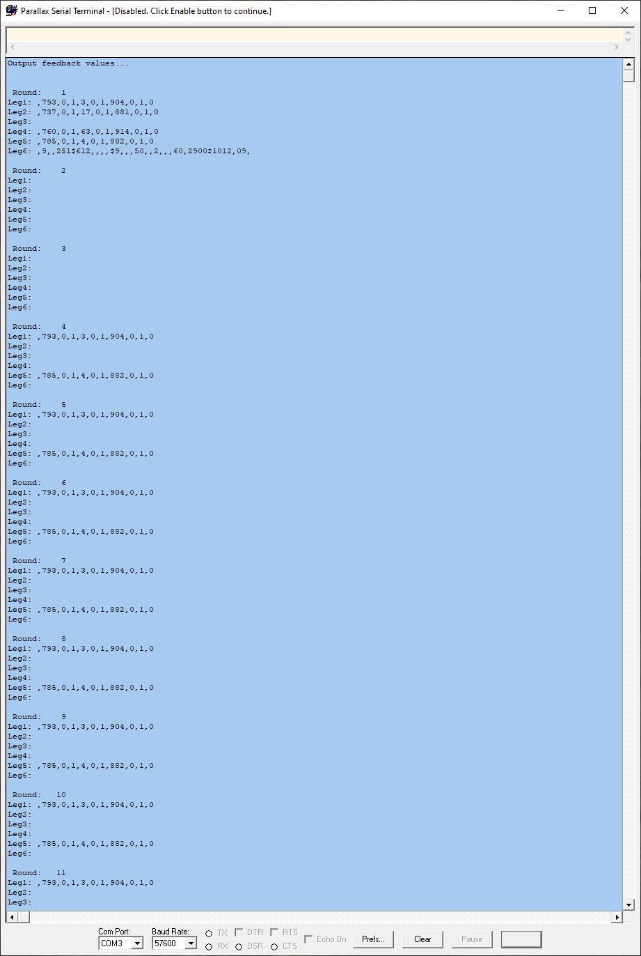
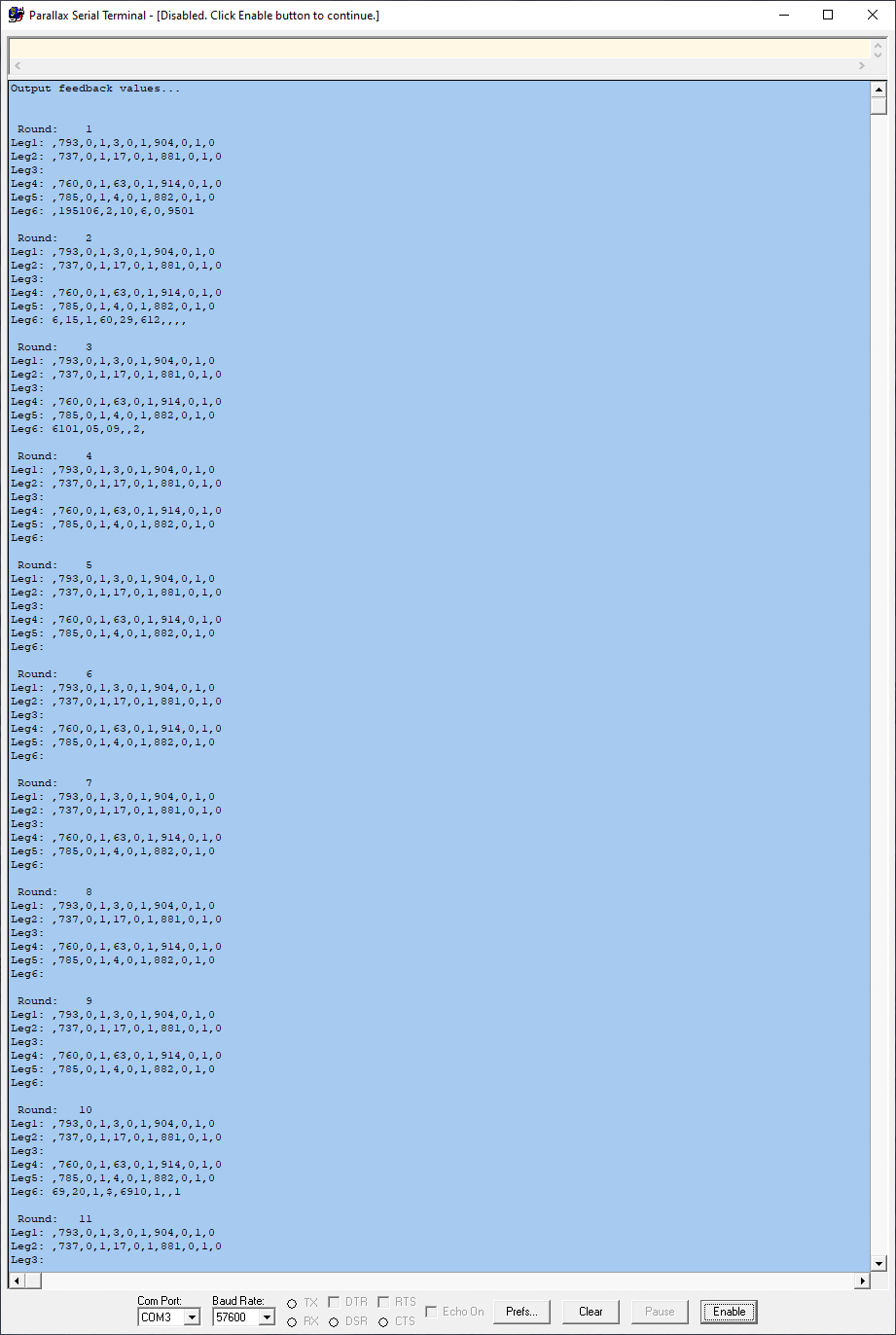
I changed the buffer size from 128 to 256 with the only difference being that it would output 256 lines to the terminal before stopping.
Next I changed the MAX_PORTS from 16 to 8 and I did get a different output, instead of Leg3 and Leg 6 being blank I got a different pattern (see Capture.png). On round 1, leg3 is blank and Leg 6 is bad data. It settles down to outputting leg1 and Leg5 correctly until round 18 where it would spit out data for Leg3 that was incorrect data. It stops again at round 53 which if I added up all the printed lines would probably add up to 128 lines.
For this next run I incremented the BUF_SIZE of each port by 2 (BUF_SIZE + 2, BUF_SIZE + 4, BUF_SIZE + 6, ...) and got good data on 4 outputs, Leg1, Leg2, Leg4, Leg5. Leg6 showed up in the first 2 rounds but was bad data (all data should look very similar in value and same # of items).
@DiverBob
From the first post...
Each P1 outputs 27 characters "$,nnn,n,n,vvv,v,v,ccc,c,c,x" where the last x is .
27*10 bits at 57600 baud gives 270 bits at 17.36us so 270 * 17.36 = 4.687ms
6 legs * 4.687ms = 28.125ms
How often do your legs repeat an output?
Remember you are outputting to PST at 57600. Perhaps try cranking this up to 115,200 or 921,600 or 2,000,000 and see if this has any effect on the results.
You can use loadp2 to load and run the binary compiled with proptool on W10.
Run the Command Prompt, and perform similar steps to these where required
'''
Microsoft Windows [Version 10.0.19042.928]
(c) Microsoft Corporation. All rights reserved.
C:\Users\Ray>cd c:\p2_retroblade2
c:\P2_RetroBlade2>C:\P2_RetroBlade2\loadp2 %1.binary -b921600 -t -SINGLE
'''
What you're doing here is to change directory to the directory where your binary (and loadp2) resides
In line 60:
'Define serial ports ... (1 fdx uart serial ports)
'---------------------------------------------------- ------------------------------
  RX_PORT_NUM = 0 'rx port [n]
  RX1 = 63 {I} 'rx pin: programming / debug
  TXBUF_SIZE = BUF_SIZE
'---------------------
  TX_PORT_NUM = 1 'tx port [n]
  TX1 = 62 {O} 'tx pin: programming / debug
  RXBUF_SIZE = BUF_SIZE
'---------------------------------------------------- ------------------------------
  RX2_PORT_NUM = 2 'rx port [n]
  RX2 = 15 {I} 'rx pin: 2nd serial port - Leg # 1 feedback
  RXBUF2_SIZE = BUF_SIZE
'---------------------
In RX_PORT_NUM you use TXBUF_SIZE and
in TX_PORT_NUM you use RX_BUF_SIZE, but
they may not matter.
But in line 234
by serL3 you use RX4 but
for serL6 you use RX4 too, it should be RX7
Maybe that's what's wrong?
I do not know much about P2 yet as I do not have any.
Yours sincerely
edit: In file from post number 3
Good catch!
I didn’t look at the posted code.
Good catch, I’ll fix that and see if it makes a difference.
Today I’ll change the P1 output baud rate to a higher baud and see how that impacts the output per Ray’s suggestion.
The P1 code has the feedback data for each leg in a continuous loop on its own cog. It just grabs data from various global parameters (gets motor angle, motor direction, motor error code for each motor (9 items separated by commas, with the last data point being whether or not the leg is touching the ground), formats the data and then outputs the info. There is no syncing between the individual P1 controllers so the feedback output timing between P1 controllers can vary, hence the use of a start character, ‘$’, to signal the start of the data sequence. This way the master (P2 computer) can miss feedback data with no issues while it is dealing with feedback from other legs. Feedback values only change based on the speed the motors are turning which is considerably slower than the speed the P2 can respond. I’ll hook the logic analyzer up and get the average time between feedback output from a P1 controller.
You added this to your last response, not sure I understand what this step is supposed to be testing?
@frida, you are a genius! That fixed the Leg3 and Leg6 output problems! Great catch, I'd looked over the setup a couple of times but somehow that eluded me each time, thank you for your help! I attached a snapshot showing the data correctly being displayed on the PST.
The next problem to tackle is why the data stops outputting when it reaches the BUF_SIZE value.
with BUF_SIZE = 127, I got 21 rounds of 6 values so 126 lines. Changing BUF_SIZE to 256 increased the number of rounds to 42 (252 lines). It appears the BUF_SIZE value is related somehow (also tested BUF_SIZE = 512 with # of rounds increasing to 85). Going to do some digging around the code and see if I make any other mistakes in the Spin2 code.
Diver Bob,
Let me start with saying that I do not own nor program for the P2, however I have use circular buffers in the past. The fact that you can increase the size of the buffer and increase the numbers of correct responses, leads me to believe that the problem lies with the circular buffer pointers. I always use a buffer size that was on an even byte or word boundry so that to go back to the besinning of the circular buffer, I would just zero the highest order bits, which would send it back to the physical begining of the buffer. If I used an 8 bit buffer, when the 9th bit became 1, I would zero it out which would then point back to the original begining of the buffer. i.e. 000000000 011111111,100000000,reset the first 1 back to zero goes back the the front of the buffer. As I recall, if was a simple matter of and $0FF.
EDIT
I went back and opened your file and looked at your code for the circular buffers. I saw that you used both a head pointer and a tail pointer in the transmit buffer, but in the receive buffer, I could only see a p_head, which I took to be the head pointer. I found no tail pointer. Could that be the problem
Jim
The purpose of this is to load your PropTool compiled program with loadp2.exe that comes with flexprop. It uses the windows command prompt as a terminal following downloading. Replace %1 with your binary name. This should rule out any problems with PST.
WTG Frida. Bob, so pleased this has fixed one problem.
Bob, BTW I was suggesting using a buffer size that was not on a power of 2’s boundary, but preferably on a long boundary eg 160 not 128 or 256.
Seems you need to check your circular buffer code too. See my receive code for the way to do it.
It's just a feeling, I do not know if it works, but could you try to change the following line:
with:
in the file:
In the
'+-----------------------------------------------------------------------------+
'+ routines for receive +
'+-----------------------------------------------------------------------------+
Cluso99, Actually I’m using your serial code (mpz_fullduplexserial.Spin2) as I couldn’t get my multi-port version to work properly! I’ll be looking over your rx code and see if I can figure out how your circular buffer works. RS_Jim noted that he didn’t see the tail pointer on the rx section so I’ll be looking for that first.
I looked at this part of the object and didn't see anything particularly wrong here, new is just the tail value +1 and is used if at the end of the buffer to reset the buffer.
Just for fun I made the change with your suggested change which allowed the output to stream as long as I was watching but the output was randomly blank, only 1, 2 or 3 lines would show up but many rounds of just blank data. So that isn't the answer but it gave me some ideas to try out.
@Cluso99 - I changed the BUF_SIZE = 160, no change other than I got to 26 rounds.
@Cluso99 - The test @frida suggested above had me thinking about modifying the rsStr(stringptr) method so that when the ending 'CR' of any string pointer is reached, then reset the rx end pointer to equal the start pointer. This way the data never fills up the buffer. I tried a few variations of that idea that didn't work and I think I probably am not properly understanding how you are using the start and end setup. Do you think something along this line would work?
pub rxChr() : chr | p, head, tail, new '' Pulls byte from receive buffer if available '' -- will wait if buffer is empty p := rxport ' rx port[n] repeat while long[p_port_params][4*p+0] == long[p_port_params][4*p+1] ' wait while buffer empty (head=tail?) tail := long[p_port_params][4*p+1] ' tail chr := byte[tail] ' get a char tail := tail + 1 ' update tail pointer if tail == long[p_port_params][4*p+3] ' new=end? (end of buf?) tail := long[p_port_params][4*p+0] ' y: new=start long[p_port_params][4*p+1] := tail ' update tail ' if (noecho == 0) and (0 <= txport < MAX_PORTS) ' txChr(chr) ' echo@DiverBob
I'll have to look at the code later - at work in between tasks atm.
IIRC there is a description of how the buffer works in the driver code.
Head is a long address pointing to the current start of the data in the buffer (only gets updated when a byte is removed from the buffer)
Tail is a long address pointing to the current end of the data in the buffer (only gets updated when a byte(s) is inserted into the buffer)
Start is a long address pointing to the first byte in the total buffer
End is a long address pointing to the first byte after the end of the total buffer (ie is the start + buffer size)
After the head gets incremented, before it is written back, the code checks if it equals the End, and if so is replaced by the start, and then the head is written back. The same happens for the Tail.
This is NOT the same as the method used by P1 code, and IIRC jonnymacs P2 code, uses offsets rather than actual hub addresses.
Running more tests today. I modified the P1 code I used originally for inputting the string and it works great, no issues
pub getcmd(hdr, pstr, len, port): result | idx, k, char                              'routine designed by Jon McPhalen
' get command from serial stream
' hdr is required header character
' pstr is pointer to string space for command
' len is maximum length of input (buffer len-2)
' port (1-6) selects serial object
  repeat
    case port
      1: char := serL1.rxtime(10)
      2: char := serL2.rxtime(10)
      3: char := serL3.rxtime(10)
      4: char := serL4.rxtime(10)
      5: char := serL5.rxtime(10)
      6: char := serL6.rxtime(10)

    if char == -1
      result := -1
      quit
    byte[pstr][0] := (k := char)                                             ' get char from stream
    if (k == hdr)                                                               ' if header
      quit
  if result == 0
    idx := 1                                                                      ' set starting index
    repeat while (idx < len)
      case port
        1: char := serL1.rxtime(10)
        2: char := serL2.rxtime(10)
        3: char := serL3.rxtime(10)
        4: char := serL4.rxtime(10)
        5: char := serL5.rxtime(10)
        6: char := serL6.rxtime(10)

      if char == -1
        quit
      byte[pstr][idx] := (k := char)                                           ' get char from stream
      if (k == 8)                                                                 ' if backspace
        idx := --idx #> 1                                                         ' backup
      elseif ((k == 0) OR (k == 13))                                              ' if 0 or CR, quit
        quit
      else
        ++idx                                                                     ' advance pointer
    byte[pstr][idx] := 0                                                          ' terminate string
@Cluso99 - The problem appears to be related to the mpx_fullduplexserial.spin2 implementation of RxStr() code. I played around with it some more but still couldn't get it to work for me.
In the meantime I will use the working code and continue on with the next communications item, using transmit to send movement commands to the 6 P1 leg controllers. This uses just a single transmit pin wired to all 6 controllers. The controllers listen for a movement command directed to them specifically so I will be converting P1 code over to P2 and testing that operation.
Another feeling.
Could you try lowering the baud from P1 to 9600, to see if there is buffer overflow in P2.
The ring buffer in P2 does not stop even when it is full, but continues unabated.
Since you are testing both an hdr grade and a CR grade, these can be overwritten.