

I'm not to smart when it come to smart pins (Serial SBUS Driver)
 iseries
Posts: 1,547
iseries
Posts: 1,547
Ok, I am trying to build an SBUS driver for the P2 using smart pins.
SBUS is serial data at 100k baud with Even parity and two stop bits.
So to configure a smart pin I would use 10 bits and threw away the parity and one stop bit right?
Here is the code I used:
void DoRead(void *par)
{
    int i;
    uint16_t c;
    Head = 0;
    Tail = 0;
    int bitperiod = (_clkfreq / 100000);
    int bit_mode;

    bit_mode = 9 + (bitperiod << 16);
    _pinstart(SPIN, P_ASYNC_RX, bit_mode, 0);

    Lock = _locknew();

    i = 0;
    while (1)
    {
        c = 0;
        while (c == 0)
            c = _pinr(SPIN);

        c = ~(_rdpin(SPIN) >> 24);
        Buffer[Head++] = c;
        Head = Head & 0x3f;
        if (c == 0xf0)
        {
            //DoChannel();
            //Tail = Head;
        }
    }
}
This code however does not work.
The following assembly language program does work though:
void DoInput(void *par)
{
    int baud;
    uint16_t c;
    int pin;
    int bitperiod = (_clkfreq / 100000);
    int wcnt;
    int i;

    wcnt = bitperiod / 2;
    Head = 0;
    Tail = 0;
    pin = SPIN;

    while (1)
    {
        __asm volatile {
            loop1   testp pin  wc
            if_nc   jmp #loop1
                    mov i, #10
                    mov c, #0
                    waitx wcnt;
            loop2   waitx bitperiod
                    shl c, #1
                    testp pin  wc
            if_nc   or  c, #1
                    djnz i, #loop2
                    shr c, #2
        }
        Buffer[Head++] = c;
        Head = Head & 0x3f;
        if (c == 0xf0)
        {
            DoChannel();
            Tail = Head;
        }
    }
}
So when configuring an async pin how do I account for the parity bit and two stop bits?
Mike
Comments
Doesn't work as in nothing received, or messed data?
That doesn't look right. You're expecting 10 bit words in little-endian. So parity and first stop bit are last to arrive and shifted in to msb. Which means you've removed the bottom two bits of the data byte while retaining the parity and stop bits.
And the binary inversion shouldn't be needed either.
For a receiver you don't need to receive additional stopbits, it's just a longer idle time between the serial bytes.
So initialize the smartpin with 9 bits (8 data + parity):
To read the 9 bits from the smartpin and mask the 9th bit:
Andy
Out of interest, what is SBUS? Got a link? Google has nothing of note.
My Google found it - it's a serial protocol for Futaba servos.
@evanh ,
Here is a link to an example of SBUS.
The SBUS protocol is inverted from normal. So a High is a low and a Low is a high.
I do receive data but they are the wrong values. I guess one would need to build a serial transmitter with known values so that code could be further tested.
Mike
As compared to plain asynchronous serial comms, and beyound the presence of even parity and two stop bits, SBUS uses inverted voltage levels, so one would need to relly on PAD I/O mode-control bits (M[7:6]), inverting both Input and output logic leves, in order to use smart pins asynchronous receive and transmit functions.
Yes, may as well use the hardware inversion since it's there.
@evanh ,
I thought of that as well but that doesn't work since the signal is not inverted. IE, the start bit is positive as well as the stop bits. Only the data is inverted.
Mike
Really? That's odd. The usual reason for saying it's inverted is because they've removed one of the hardware inversions in the serial hardware interface. RS232 normally has two inversions in the mix, one at transmitter end and the other at the receiver end.
Yeah, this is it from the that link - "The SBUS protocol uses an inverted serial logic". I read that as talking about the electrical interface.
I think you'll find you won't need to invert for your testing - in hardware or software. It'll actually depend on the electrical side of things as to whether you do or don't invert. And then you do it with the hardware config bits.
Its even worse: there seems to be at least two "flavors" of SBUS.
One used with Futaba servos, where voltage levels are "inverted", as compared to plain asynchronous serial interfaces.
The other version, used with Frsky hardware, which I'm still trying to understand...
https://youtube.com/watch?v=IqLUHj7nJhI
P.S. Another good reference:
robotmaker.eu/ROBOTmaker/quadcopter-3d-proximity-sensing/sbus-graphical-representation
@iseries You and I seem to be writing similar code, but in different languages. I am also working on an SBUS object, but I'm working is Spin2. I've decided to skip the use of smart pins so that the transmitter can add the proper stop bits. This is not tested yet, but is the direction I'm going.
tx_sbus         ones      t1, txdata                    wc      ' count ones for parity
                bitc      txdata, #8                            ' add parity bit
                shl       txdata, #1                            ' add start bit
                or        txdata, ##%110_00000000_0             ' add stop bits

                rep       #3, #12                               ' start + 8 + parity + 2 stop
                 shr      txdata, #1                    wc
                 drvnc    txd                                   ' inverted output
                 waitx    baudtix

                ret


rx_sbus         testp     rxd                           wc      ' sample rx
    if_nc       jmp       #rx_sbus                              ' wait for start

                getct     bittimer                              ' sync bit timer
                mov       t1, baudtix                           ' wait half a bit (middle of start)
                shr       t1, #1
                addct1    bittimer, t1
                waitct1

                mov       rxdata, #0                            ' clear workspace

                rep       #5, #9                                ' 5 (inst) x 9 bits
                 addct1   bittimer, baudtix                     ' update bit timer
                 waitct1                                        ' let bit timer expire
                 testp    rxd                           wc      ' sample rx
                 shr      rxdata, #1                            ' prep for new bit
                 bitnc    rxdata, #8                            ' remove inversion

               ret
Again, I'm still very much in the experimental stage and this hasn't been tested. Once I get SBUS working (for a friend who works in special effects on "The Mandalorian" and other Star Wars shows), I will probably update the code so that the interface can decide between SBUS and I-BUS (SkyFly). My understanding is that I-BUS is just an inversion of SBUS (I could be wrong).
I'm pretty sure that's not the case, Mike; everything must be inverted else you wouldn't be able to discern a start bit from the last stop bits. I did a screen cap from the video that was referenced of the frame header byte, which is 0x0F. This already has an even number of bits, so the parity bit would be 0 (before inversion).
I used Inkscape to create an overlay just so I could get this stuff straight in my head.
@JonnyMac ,
Futaba SBUS is inverted in that the signal is high between frames and a low pulse is the start bit.
With FrySky which is what your showing above the signal is low between frames and a start bit is positive but the meaning of the data is inverted in that low is 1 and high is 0.
You can't use inverted smart pin to read the data because it would expect the pin to go low for the start bit but it does not.
Mike
So, for FrySky, you would need to use non-inverted mode, but then invert the data after it's read (AFAIK, not that hard)
With respect, Mike, I believe you're mistaken. Everything I've read or seen (YouTube) about SBUS is that it is inverted from standard (true mode) serial. Have a look at all the Arduino SBUS projects floating around; every one of them inserts an inverter circuit between the RC receiver and the RX pin.
I went for my morning walk after the posts above and while considering other comments concluded we can do SBUS with smart pins. For transmitting, we will set the smart pin UART to 10 bits and always make bit 9 of the output value high; this will act as an extra stop bit. Of course, we will use INVERTED output mode for SBUS (non-inverted for FlySky).
Here's my SBUS TX setup code (Spin2).
I tested the output (by connecting to a logic analyzer) with this code:
pub sbus_tx(b, txd) | x

  org
                ones      x, b                          wc      ' count ones for parity
                bitc      b, #8                                 ' add parity bit
                bith      b, #9                                 ' add stop extra bit
                wypin     b, txd                                ' load into sp tx uart
  end
It worked as expected. With that, I added the receive side. In this case, we only need to get nine bits (again, inverted)
And here's the receive code. This checks the parity bit and on an error, causes the method to return 0 (not sure if this is a best long-term solution; again, this is test code).
pub sbus_rx(rxd) : b | x

  org
                testp     rxd                           wc      ' anything waiting?
    if_nc       jmp       #$-1                                  '  not yet

                rdpin     b, rxd                                ' read new byte
                shr       b, #23                                ' align lsb

                testb     b, #8                         wz      ' save parity bit
                and       b, #$FF                               ' strip parity bit
                ones      x, b                          wc      ' count ones for parity
    if_c_ne_z   mov       b, #0                                 ' bad parity, return 0
  end
I ran a jumper between two pins on my Eval board and gave it a go -- it works! Again, I confirmed the output of the TX pin with a logic analyzer, so I know it matches what comes out of an RC receiver. The receive code just worked.
I've attached the project code in case you want to give it a try.
I agree, that is what the scope shows.
Since this thread focuses on SBUS, maybe the title can be edited by the OP to include SBUS ? - Maybe it can become 'SBUS with smart pins'
Final test of the day. This is rough-ish code that receives an SBUS packet and decodes it. The inline code will get folded into a cog along with the channel unpacking (will convert Spin to PASM2). The screenshot is the raw packet and channel data from a 10-channel RC receiver configured for SBUS mode.
@JonnyMac ,
Well I tried your code the best I could since I don't do SPIN.
I am using pin 8 for input and with your code the screen shows this:
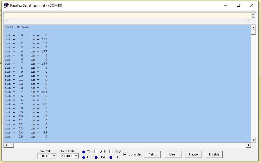
The data should have been this:
Channel: 3fb 3ea 0c4
This is the assembly code I am using:
    while (1)
    {
        __asm volatile {
                    mov i, #10
                    mov c, #0
                    mov bit, #1
            loop1   testp pin  wc
            if_nc   jmp #loop1
                    waitx wcnt;
            loop2   waitx bitperiod
                    testp pin  wc
            if_nc   or  c, bit
                    shl bit, #1
                    djnz i, #loop2
        }
        c = c & 0xff; // dump parity stop bits
        Buffer[Head++] = c;
        Head = Head & 0x3f;

        if (c == 0x0f)
            p = 0;
        Serial[p++] = c;
        if (p == 25)
        {
            DoChannel();
        }
        if (p > 26)
            p = 26;
    }
This same code is what I used on the P1.
Here is a picture of my setup:
X8R 16 Channel Setup
Mike
And it has a problem: You are receiving the bits MSBFIRST when serial devices transmit LSBFIRST. In your case, bit0 is being thrown away, bits 1..6 are backward and out of alignment, and you're using the parity bit as bit 0.
You started the thread wanting to use smart pins. Several people made good suggestions which inspired my working code. I'm guessing that you're using FlexGUI. As an exercise, I created a PASM version of my receive code to prove what I was talking about above (you have bit order flipped). Below is a screenshot running that code in FlexGUI. I've attached that update for you to try.
Here's the guts of my PASM code. Note that I'm adding the new bit into bit8 and shifting right -- this is LSBFIRST
                getct     t                                     ' sync bit timer
                mov       x, baudtix                            ' wait half a bit (middle of start)
                shr       x, #1
                addct1    t, x
                waitct1

                rep       #5, #9                                ' 5 (inst) x 9 bits
                 addct1   t, baudtix                            ' update bit timer
                 waitct1                                        ' let bit timer expire
                 testp    rxd                           wc      ' sample rx
                 shr      b, #1                                 ' prep for new bit
                 bitnc    b, #8                                 ' remove inversion
I think you'll agree, though, using smart pins is less work. For my own SBUS objects I have changed my mind and will use smart pins.
@JonnyMac ,
You are correct that the first code is processing the bits MSBFIRST which was on purpose back then on the P1. The follow-on code that decoded the bits into 11-bit data processed the data backwards and produced the correct values for each channel. Has worked well for several years now.
The latest code I posted I rearranged the code so that it input the data in the correct order and I also went back and applied it to my P1 code just so things are all in the same order. I then had to fix the Channel code so that it processed the data in the correct order.
All is working using the assembly code which has no effect on performance or resources even if you were to use a smart pin.
After all this, I still am not able to get smart pins to work.
I need to do one other thing in that 0x0f can appear in the data stream causing a miss-step and I need to try and detect that.
I also need to add locks so that all the channels are updated at the same time before reading the values.
Mike
If you want to get the data "flipped" as you were doing in the P1, this is a simple matter of a couple instructions. After the byte has been received by the smart pin and stripped of the parity bit, add these lines
.flip           rev       b                                     ' reverse bits
                shr       b, #24
Now the bits of byte b will be in reverse order and fall into the scheme you used in the past. I saw some code posted by Jason Dorie that did this; what I haven't done yet is wrapped my head around his mechanism for unpacking the bytes to position values.
If you want to skip the parity test (it seems everybody does), you can do this:
.get_sbus testp rxd wc ' anything waiting? if_nc jmp #.get_sbus ' not yet rdpin b, rxd ' read new byte rev b ' flip bits shr b, #1 ' strip parityIf you look at my code, you'll see that the receive section actually waits for the input to be quiet for 250 microseconds (2 byte periods); this is detecting the space in between packets so there is little chance of a miss-step (MODBUS and other serial protocols use this strategy). Having settled on 250 microseconds, this is that code.
                fltl      rxd                                   ' reset uart, release smart pin

.wquiet         mov       x, #250                               ' wait for lull between packets
.wq1            waitx     us1
                testp     rxd                           wc
    if_c        jmp       #.wquiet                              ' if activity, restart wait
                djnz      x, #.wq1
Note that the first instruction allows me to use rxd as a standard tri-state pin, but doesn't remove the smart pin settings; after exiting this section the pin is driven low to re-enable the smart pin UART.
I'm using a djnz loop to receive the bytes, but another option would be to start the loop with n at 0 and then use incmod to detect the end of the packet. This would allow you to check (when n == 0) if 0x0F is the first byte; if not, the code could jump back to waiting on a new p packet. I don't intend to do this.
In my own S.BUS receiver, I'm going to do this in the cog (PASM2)
I will continue testing with inline PASM2 until I get everything worked out.
@JonnyMac ,
I have completed my SBus decoder driver and have put it up on my custom libraries.
I have functions for get channel values, get adjusted channel values, and get scaled channel values.
As always I have a sample program to test the driver as well.
Mike
@JonnyMac ,
Ok, I went back and did some research and found that I was wrong about how serial works. You are correct that it starts at 3.3 volts and goes low for the start bit.
I seem to remember several years ago that people used inverters to hookup their FrSky units but never did that since the flight controller I used handled it.
Since then those brain cells have been lost and things just work.
After reviewing that I went back and programmed the smart pin with inverted A as well as 10 bits and also chopped off the top two bits to get the correct values using Smart pins. I guess it works as designed.
    int bitperiod = (_clkfreq / 100000);
    int bit_mode;

    bit_mode = 9 + (bitperiod << 16);
    _pinstart(SPIN, P_ASYNC_RX | P_INVERT_A, bit_mode, 0);
...
        c = 0;
        while (c == 0)
            c = _pinr(SPIN);

        c = (_rdpin(SPIN) >> 22);
        c = c & 0xff;
Mike
I'm glad you got it working in C -- this is the code I'm using (Spin2)
I'm porting Jason Dorie's decompression algorithm from Spin1. Since it counts on LSB-MSB flipped bytes, I do it like this and store in a hub array
rev b ' reverse rx'd byte, MSB to bit0 rol b, #8 altsb i, #.sbus_raw ' store in hub array setbyte bThis is my port of Jason Dorie's PASM1 code to unpack the [reversed] bytes of the S.BUS packet. It's working in my static test program; the next step is to move it to the live object.
I tested and found it takes about 5 microseconds (@200MHZ sys clock) to unpack and write the values to the hub. This suggests the busy flag may not be necessary, but I'm going to keep it, anyway.
' unpacks reversed s.bus packet bytes to channel values ' -- ported from Jason Dorie's Spin1 code .unpack mov ch, #0 ' first channel value index mov i, #1 ' first packet byte mov tmp, #0 ' work value mov bc, #0 ' work value bit count .get_byte altgb i, #.sbus_raw ' get s.bus byte from cog array getbyte v add i, #1 shl tmp, #8 ' prep for new byte or tmp, v ' add to work value add bc, #8 ' update bit count cmp bc, #11 wcz ' enough for channel value? if_b jmp #.get_byte ' no, get another byte mov eb, bc ' copy bit count sub eb, #11 ' extra bits (to remove) mov chval, tmp ' copy shr chval, eb ' clean-up channel value rev chval rol chval, #11 ' restore LSB position wrword chval, p_ch ' write to hub add p_ch, #2 ' advance hub pointer sub eb, #1 ' decrement for bmask bmask keep, eb ' make a mask and tmp, keep ' remove previous channel data sub bc, #11 ' update bit count incmod ch, #15 wc tjnz ch, #.get_byte ' test flags altgb i, #.sbus_raw ' get flags byte getbyte v testb v, #7 wc ' ch17 is digital if_c mov chval, ##2047 if_nc mov chval, #0 wrword chval, p_ch add p_ch, #2 testb v, #6 wc ' ch18 is digital if_c mov chval, ##2047 if_nc mov chval, #0 wrword chval, p_chI think the code could be optimized and shrunk by ~20%, even without understanding it fully: replace shl;or with rolbyte, cmp;sub;sub with cmpsub, wrword;add with wrword ptrx++ (perhaps), wrword;add;wrword with wrlong (4 long saving possible in last 11).
Cool. Show us how. As I stated, this was a [near] direct translation of Jason Dorie's P1 code. My initial goal was to get that code to work in the P2. It does. If you can make it faster, I and other beginner/intermediate assembly programmers would love to see your approach.
Okay, @TonyB_ , this is what I came up with based on your suggestions. The old code ran in 4.8us (@200MHz) and the update runs at 3.9us -- nearly 20% faster. Thanks for the tips. That said, I'd still like to see your version.
.unpack         mov       ch, #0                                ' first channel value index
                mov       i, #1                                 ' first packet byte
                mov       tmp, #0                               ' work value
                mov       bc, #0                                ' work value bit count
                mov       ptrb, p_ch                            ' point to output array

.get_byte       altgb     i, #.sbus_raw                         ' get s.bus byte from cog array
                rolbyte   tmp                                   ' move new byte into tmp
                add       i, #1                                 ' bump byte array index
                add       bc, #8                                ' update bit count
                cmpsub    bc, #11                       wc      ' enough bits for channel value?
    if_nc       jmp       #.get_byte

                mov       chval, tmp                            ' copy
                shr       chval, bc                             ' clean-up channel value
                rev       chval                                 ' flip back
                rol       chval, #11                            ' restore LSB position
                wrword    chval, ptrb++                         ' write to hub

                bmask     keep, bc                              ' make mask to preserve unused bits
                shr       keep, #1                              ' correct the mask
                and       tmp, keep                             ' remove previous channel data

                incmod    ch, #15                       wc      ' bump channel
                tjnz      ch, #.get_byte                        ' if not done, get next byte

                altgb     i, #.sbus_raw                         ' get flags byte
                getbyte   v

                mov       tmp, #0                               ' clear ch17/ch18 workspace
                testb     v, #7                         wc      ' ch17 is digital
                bitc      tmp, #00 + (10 << 5)                  ' 0 if nc, 2047 if c
                testb     v, #6                         wc      ' ch18 is digital
                bitc      tmp, #16 + (10 << 5)                  ' 0 if nc, 2047 if c
                wrlong    tmp, ptrb
Edit: The flags section updated based on suggestion from @evanh (saves a few lines and 0.3us in execution time).