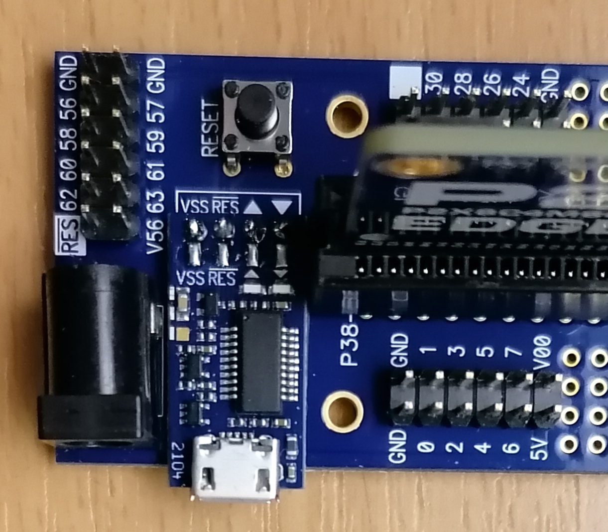
P2 Edge Mini & PROP PLUG my first impression
 pic18f2550
Posts: 400
I find the Edge Mini handy
But the lack of 24 pins puts a mighty damper on the joy.
Will there be a version where all 64 pins are available?


Comments
It think you are referring to this product ? : https://www.parallax.com/product/p2-edge-mini-breakout-board/
There is a rough design idea to make a similar / simple breakout with all the I/O pins.
It would follow (and be useful for) the P2 Cube project. That is something to come back to as the P2 Cube progresses, and could happen rather quickly once all the requirements are figured out.
If it happens, I will post the initial layout here so that anyone can chime in with thoughts before anything gets ordered.
Yeah, it's about the part.
What are the many soldering eyes between the pin rows for ?
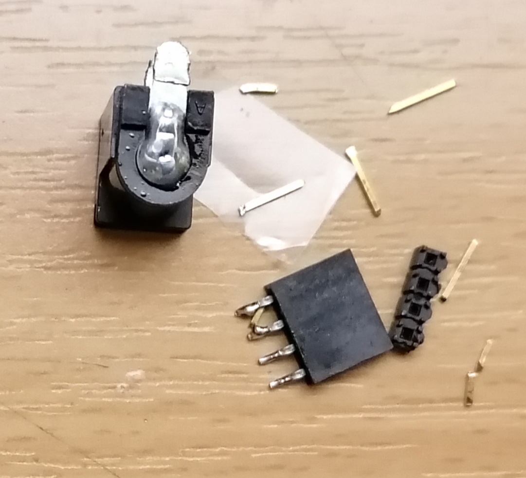
I will remove the power socket because of loose contacts.
The power cable I will solder directly to the board.
I will solder the PROP PLUG directly onto the board and fix it with two-sided adhesive tape.
The soldered bushing is already showing fatigue properties.
The old PROP PLUG was not only smaller but also mechanically Stabieler.
Even if he loses his plastic housing from the socket from time to time.
The new PROP PLUG protrudes far beyond the edge of the board.
The 4 mounting pins are not soldered to the circuit board.
You can see through the soldering eyes.
Whether the durability is given?
I will solder something in any case.
The cable is not exactly light and Flexiebel.
This is my first impression of the particle.
There are 2pins under the socket that accept a standard 5mm or 5.08mm pitch screw terminal if you'd prefer to fit that.
Two-sided tape is highly recommended for fixed use. We included four TH pads under the 4-way connector to provide some options like your describe, and for customers that would rather install pogo pins or directly solder.
could you share a photo? Not sure which part you mean.
Visually it looks smaller (I agree!), but it's actually the same dims, except for the microUSB socket that has the sticking-out wings to help guide the connector in. I guess that makes it ~1mm longer. I just compared two or three here- some of the new ones are a hair narrower, some are a hair wider, due to the v-score cutting tolerances.
That was intentional to reduce the PCB size and cost for everyone. We placed it beside the Barrel jack, as that sticks out too, but a similar amount.
If you mean the microUSB socket, then they are, just not so obvious due to the mask paint on the outer edges. Also, the underside of the socket has a very thick and wide band of solder, bonding the socket to the PCB. You will be able to measure continuity between the VSS pin and the microUSB shell.
Thanks for your feedback. It's always appreciated, and we always remember constructive feedback to keep improving. For sure- I will check with production to see how the look of the USB socket legs can be improved next time. It is solid as-is, but I think you are right that the look is also important.
A few pictures to better illustrate the problem areas.
Missing solder on the pins
Missing solder on the pins
Overhang
Too weak
What are the soldering sheets used for?
Those are for user circuits.
@pic18f2550
I think you will find that there are huge soldered pads under the USB-C shell wheich means that the thru hole legs do not really need to be soldered at the whole USB shell is securely anchored to the board.
@Cluso99
I'm thinking about discarded SMD pads.
This should already hold for normal use.
Only the legs are not only intended for fixation, but also for the force absorption of the rellatively rigid cables.
But if I can solder it up, I don't care.
I have found the loose contact.

It is the pin in the socket.
Just solder it on and it's gone.😁
But I had already soldered in a new one.
I have removed the socket from the PropPlug.

I stuck it to the board with double-sided adhesive tape.
The pin headers were straightened, shortened and soldered.
It doesn't look so dangerous now.😇
Pin 59 reacts strongly to electrostatic fields.
This should cause problems when booting.
Or are there internal countermeasures for this?
@pic18f2550: If you did that with the older style of prop plug it would end up about flush to the edge. Still would need secure adhesion to the board. The contacts on the plug don't stand up to much sheer stress, i.e. an accidental bump for one. (Been there, lifted all pads with the connector)
I have purchased also 64018 RevA, Just the edge socket, PCB and pins for all pins on the edge (I believe) accessible. It is bare bones, no reset switch, no large voltage connectors (just gotta pin it like all else), so you go to extremes. What would be a nice RevB would be a barrel connector into a regulator that would go from 6-16 or 12/24V to 5V for the edge (to enable running everything from 12/24V, single external supply). As I mentioned below, KEY the things!! I just know I will reinstall the edge backwards on a late nite project or repair. A reset circuit. Not worried about the rest. I like the edge itself, and if I want a SD card, I can attach one and green-wire it. Yes, it would not be as cheap as a roll your own, but if I can do all from one supply relays, motors, etc from one supply, works for me. One of the CT OEMs I service has a +48V supply and all is derived at the board level from that. Yeah, not cheap again, but simple and reliable I guess.
@VonSzarvas, I still would like to see an off center key slot in the edge module. And/or a much more visible silkscreen noting orientation/Pin1