Shop OBEX P1 Docs P2 Docs Learn Events
Propeller P1 & P2 serial data performance — Parallax Forums

Propeller P1 & P2 serial data performance
anyone have at comparison table of P1 & P2 performance?
I'm thinking about:
max clock speed for P1 SPI compaired against P2, using SPIN object code.
max clock speed for P1 SPI compaired against P2, using Assembler object code.

also would be nice with same for I2C & UART.

«1

Comments

  • uhm idk about spin, but using PASM,

    Chip Peak(!) SPI clock rate
    P1 (nominal 80 MHz) 20 MHz
    P1 (overclocked 104 MHz) 26 MHz
    P2 (nominal 175 MHz) 87.5 MHz
    P2 (realistic 250 MHz) 125 MHz
    P2 (overclocked 320 MHz) 160 MHz

    To note is that the P2 can actually sustain those rates for transfers longer than 32 bits.

  • I don't have any comparison other than for the P2 I have had to add some waits in order for the device to work. The pin would change to fast for it to be recognized.

    Mike

  • I need both SPIN and Assembler maximum speed.
    I have some code working well, using SPI assembler object at max 1MHz bus speed (Using P1 80MHz).
    Now I want to use that cog for other things, and use a SPI Spin object, but I'm hoping not to reduce SPI bus speed too much.

    I also in other projects have had same question for I2C.

  • How fast it will go will surely depend on your exact code. On P2 you'd probably want to use smartpins, in which case it won't matter much whether you use Spin or PASM, the hard work is done by the pins and so there won't be much speed difference. If you're bit-banging, I can't give you exact numbers (it'll depend on how you write your code) but my bit-banging benchmark that tries to act like an SPI gives about 0.5 Mbits/second on P2 for Chip's Spin2, and 12.8 Mbits/sec for flexspin, with a clock speed of 180 MHz.

    PASM will presumably be a bit faster than flexspin since it'll be all COGEXEC rather than some HUBEXEC, but it won't be a huge difference I don't think.

    Certainly if you use flexspin a sustained 1 MHz bus speed is no problem at all for Spin2 code. If you use the bytecode interpreter you may need to crank up the clock speed and write your code very carefully, but I think you probably could bitbang 1 MHz -- but even better would be to use the smart pins.

  • Cluso99Cluso99 Posts: 18,069
    edited 2021-02-28 19:47

    In P2 I can send and receive SPI (SD Card) using pasm inside a cog at one bit every 4 instructions (most P2 instructions are 4 clocks. I have unravelled the code to sustain this rate for the whole 512 bytes. So 8 clocks per bit at 200MHz is 25MHz. I am not using smart pins. BTW P2 can go faster - I tested the SD at 360MHz which is 45MHz.

    Now in spin2 you can inline pasm so you could send/receive at these speeds although overall throughput is going to vary due to the spin code surrounding it.

    On P1, the same 4 instructions would be 16 clocks, so at 100MHz would be 6.25MHz.

  • @Cluso99 said:
    In P2 I can send and receive SPI (SD Card) using pasm inside a cog at one bit every 4 instructions (most P2 instructions are 4 clocks. I have unravelled the code to sustain this rate for the whole 512 bytes. So 8 clocks per bit at 200MHz is 25MHz. I am not using smart pins. BTW P2 can go faster - I tested the SD at 360MHz which is 45MHz.

    Now in spin2 you can inline pasm so you could send/receive at these speeds although overall throughput is going to vary due to the spin code surrounding it.

    On P1, the same 4 instructions would be 16 clocks, so at 100MHz would be 6.25MHz.

    On P1 i guess you mean it is also running pasm?
    Do you know how fast SPI clock on P1 could be running with only spin code?

  • evanhevanh Posts: 16,029

    Your best bet is to use Eric's spin compiler tools above. It'll spit out much faster code than what Proptool can give you.

  • Cluso99Cluso99 Posts: 18,069

    @MAElektronik said:

    @Cluso99 said:
    In P2 I can send and receive SPI (SD Card) using pasm inside a cog at one bit every 4 instructions (most P2 instructions are 4 clocks. I have unravelled the code to sustain this rate for the whole 512 bytes. So 8 clocks per bit at 200MHz is 25MHz. I am not using smart pins. BTW P2 can go faster - I tested the SD at 360MHz which is 45MHz.

    Now in spin2 you can inline pasm so you could send/receive at these speeds although overall throughput is going to vary due to the spin code surrounding it.

    On P1, the same 4 instructions would be 16 clocks, so at 100MHz would be 6.25MHz.

    On P1 i guess you mean it is also running pasm?
    Do you know how fast SPI clock on P1 could be running with only spin code?

    Spin can be 20-50 times slower. As Evan said, FlexSpin will compile spin to pasm so while you may not get full pasm speed it will be much faster than the spin interpreter will do, but it will be a much bigger program.

  • Thanks everybody.
    My program is already very large, so I doubt flexspin will be the solution.
    I will make some speed test with P1 SPI spin object, and hope the bus speed will be enough, so I can free a cog for some other things.
    (Hopefully I can use P2 for next project. I have a P2 eval board just waiting for time to play with it).

  • Just made a test using P1 SPI.spin from library.
    Fastest speed of SPI clock is just under 12KHz.
    Way too slow for my applikation.
    I will find another way to spare one cog.
    Thanks everybody.

  • Cluso99Cluso99 Posts: 18,069

    Perhaps if you describe what you're doing and what runs in each cog we may be able to help.

  • MAElektronikMAElektronik Posts: 96
    edited 2021-03-02 17:44

    @Cluso99 said:
    Perhaps if you describe what you're doing and what runs in each cog we may be able to help.

    I'm happy to read you are ready to help. Thanks :)
    I already found another solution. I had two cogs running RS485, but as RS485 don't need to be douplex, I can free one of these cogs.

    Now i can expand my touchscreen project.
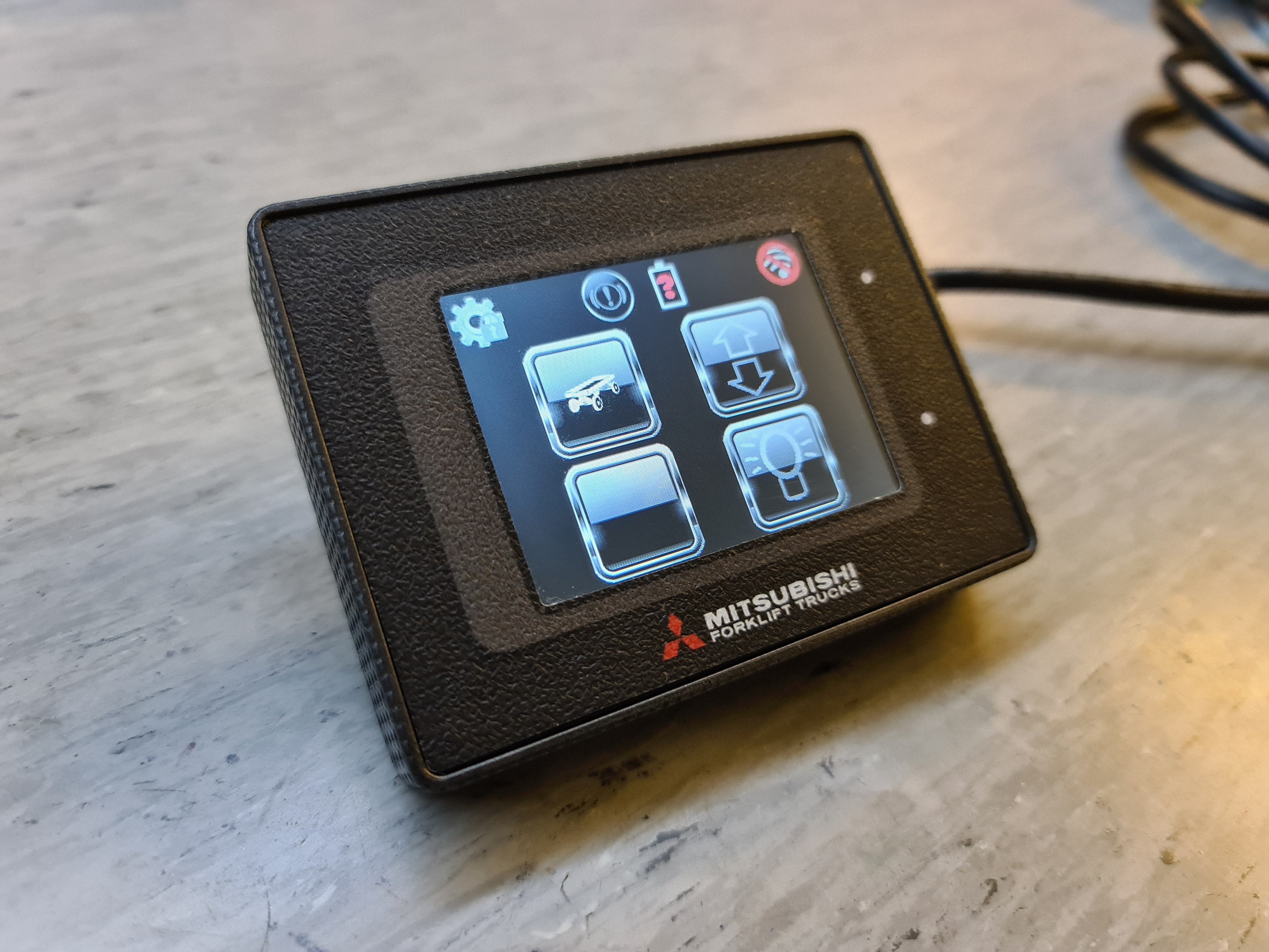
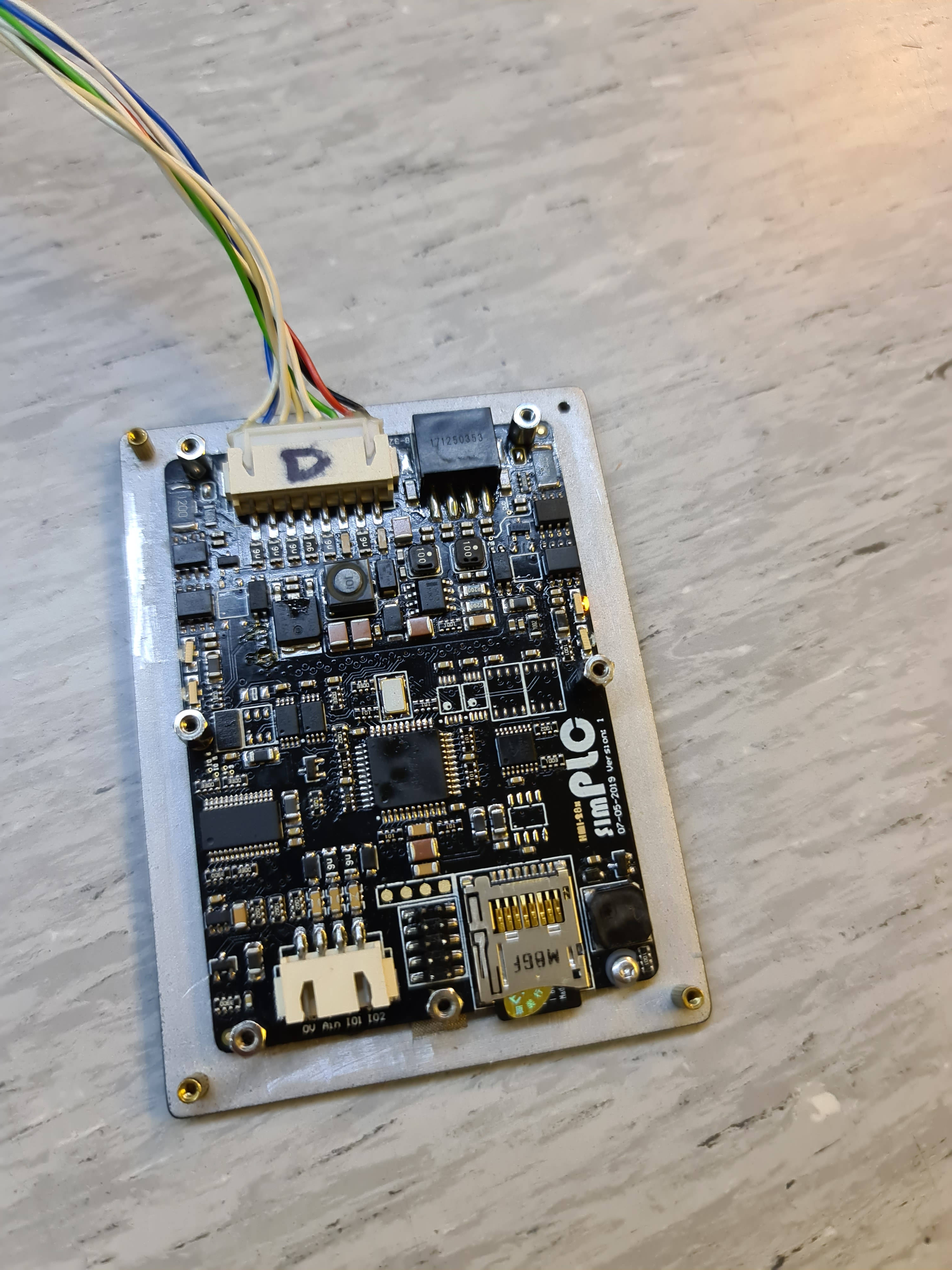
    Here are some pictures:

  • Cluso99Cluso99 Posts: 18,069

    Is that your pcb? If so, looks very professional :)

  • @Cluso99 said:
    Is that your pcb? If so, looks very professional :)

    Yes it is one i designed.. Thanks 😊

  • Cluso99Cluso99 Posts: 18,069

    Then congratulations. I see nice routing, bulk and bypass caps, a switch mode power supply, etc. Tight pcb.
    Did you route it yourself? If so, which software?
    Did you assemble it yourself or professional assembly? If yourself, what facilities do you have?
    I see the LHS upper LED didn't quite straighten when reflowed. As you obviously know, often better to leave alone as it will still work fine.

    BTW Don't answer if you consider proprietary. I am just an old EE being curious ;)

  • @Cluso99 said:
    Then congratulations. I see nice routing, bulk and bypass caps, a switch mode power supply, etc. Tight pcb.
    Did you route it yourself? If so, which software?
    Did you assemble it yourself or professional assembly? If yourself, what facilities do you have?
    I see the LHS upper LED didn't quite straighten when reflowed. As you obviously know, often better to leave alone as it will still work fine.

    BTW Don't answer if you consider proprietary. I am just an old EE being curious ;)

    Thanks.. I'm not a very good programmer, but I'm
    able to modify and extend some of the demos from obex, but from that I learn a lot(I also learn a lot from all the very good youtube videos with Johnymac. I'm best as a hardware engineer. Have been using Altium protel since it was on flopydisc, now I'm using Altium designer. This product was fully EMC tested to meet automotive CE compliance. I have access to a Neoden4 PnP machine, but I think PCB on picture is a hand soldered beta version, as the final version has comformal coating and is not that photo friendly.
    This product is developed for a small department of Mitsubishi in Denmark who sell forklift trucks, but I have the rights to use it for other purpose as well.
    Is i a touchscreen remote used to wirelessly controll four enclosed trailers with a lot of functions such as turn signals, brake lights, blitz warning light, floodlight, parking light, but it also control an electric door opener on each trailers.
    This way the operator can stay inside the vehicle when disconnecting the trailers and start unloading the products.

    This display is connected via RS485 to a companion module with input and outputs and radiomodule. It has also CANbus but we don't use it for this project.
    It has also a G-force sensor so it can log if operator is driving hazardly. There is feedback if any output is disconnected from load in case of blown bulbs.

    Frankly it is a HMI and a PLC, and could be used for anything with another firmware.

  • MAElektronikMAElektronik Posts: 96
    edited 2021-07-03 07:40

    This is the companion modules.
    It is also using a P1 chip 😊
    It is same module installed on forklift truck and also on each trailer. I use same firmware, and made it detect a dip-switch if it is transmitter or receiver.

  • @Cluso99 said:
    Is that your pcb? If so, looks very professional :)

    +1
    Thanks for sharing the photos. Those look fantastic!

  • Cluso99Cluso99 Posts: 18,069

    @MAElektronik
    Excellent work :)
    Always great to see pics of commercial products using the props!

    We built a commercial telescope controller that I designed. It uses 3 P1's. The initial EMI testing showed failure on the two pins where we were using PWM. One was driving the LED backlight on an LCD, and forget the other. Fortunately I was able to modify the values and software to reduce the EMI to a pass level without a pcb revision. Unfortunately we didn't sell huge numbers tho.
    One of the P1's was based on my RamBlade design which has a 512KB SRAM attached and dedicated to run Catalina C to manipulate the large star/etc databases on the attached SD Card.

    While each micro could have used a different micro, it was easiest and quickest, and enjoyable too, to use the P1. It's always better if you can reduce the BOM too.

  • @"Duane Degn" said:

    @Cluso99 said:
    Is that your pcb? If so, looks very professional :)

    +1
    Thanks for sharing the photos. Those look fantastic!

    Thanks for your kind feedback

  • @Cluso99 said:
    @MAElektronik
    Excellent work :)
    Always great to see pics of commercial products using the props!

    We built a commercial telescope controller that I designed. It uses 3 P1's. The initial EMI testing showed failure on the two pins where we were using PWM. One was driving the LED backlight on an LCD, and forget the other. Fortunately I was able to modify the values and software to reduce the EMI to a pass level without a pcb revision. Unfortunately we didn't sell huge numbers tho.
    One of the P1's was based on my RamBlade design which has a 512KB SRAM attached and dedicated to run Catalina C to manipulate the large star/etc databases on the attached SD Card.

    While each micro could have used a different micro, it was easiest and quickest, and enjoyable too, to use the P1. It's always better if you can reduce the BOM too.

    Thanks.. your RamBlade looks very nice too.

    3x P1's.. that must have been some sufisticated equipment, one single P1 is very powerfull i think.
    Sadly I don't see any other on Danish electronics forums using props, and no one seems to have knowledge of parallax, when I share pictures and proudly tell about using proppeller in my projects.
    I don't mind using a P1 while knowing it ads largely to the BOM cost. I could use a cheaper microcontroller, but it is easier for mee who isn't a skilled software shark, only to learn one programming language (SPIN and a little bit of PASM).

    I like your story about modifying PWM in code to pass EMI test without hardware change.. I found that inserting a 100 Ohm resistor in series on every IO will reduce EMI greatly from the P1, it also protects the pin from ESD on FFC cable to daughter board.

  • Cluso99Cluso99 Posts: 18,069

    @MAElektronik said:

    @Cluso99 said:
    @MAElektronik
    Excellent work :)
    Always great to see pics of commercial products using the props!

    We built a commercial telescope controller that I designed. It uses 3 P1's. The initial EMI testing showed failure on the two pins where we were using PWM. One was driving the LED backlight on an LCD, and forget the other. Fortunately I was able to modify the values and software to reduce the EMI to a pass level without a pcb revision. Unfortunately we didn't sell huge numbers tho.
    One of the P1's was based on my RamBlade design which has a 512KB SRAM attached and dedicated to run Catalina C to manipulate the large star/etc databases on the attached SD Card.

    While each micro could have used a different micro, it was easiest and quickest, and enjoyable too, to use the P1. It's always better if you can reduce the BOM too.

    Thanks.. your RamBlade looks very nice too.

    3x P1's.. that must have been some sufisticated equipment, one single P1 is very powerfull i think.
    Sadly I don't see any other on Danish electronics forums using props, and no one seems to have knowledge of parallax, when I share pictures and proudly tell about using proppeller in my projects.
    I don't mind using a P1 while knowing it ads largely to the BOM cost. I could use a cheaper microcontroller, but it is easier for mee who isn't a skilled software shark, only to learn one programming language (SPIN and a little bit of PASM).

    I like your story about modifying PWM in code to pass EMI test without hardware change.. I found that inserting a 100 Ohm resistor in series on every IO will reduce EMI greatly from the P1, it also protects the pin from ESD on FFC cable to daughter board.

    Thankyou.

    Sometimes commercial projects are not price sensitive, but time to market is. The prop(s) shine here because they are so easy to program making development quick. The use of objects in P1 make this chip simple to add in other libraries without the need to worry about interaction between the various libraries used - separate cores and no interrupts.

    In my case, using 3 P1's made it easier still. I needed all pins for the SRAM and SD interface (we use a large Catalina C program and database), leaving 2 pins to talk to the second P1 which was the "controller" and interface. The 3rd P1 handled just the custom LCD (Red 4 lines x 20 characters IIRC) and custom keypad in its' own box, and communication back to the "controller". It just made things simple and easy. So yes, in each case, a different micro could have been used. So we have simpler BOM that cost a bit more, but as I said, cost was not an issue. And we bought the P1's for under $5 in quantity.

  • @Cluso99 said:

    @MAElektronik said:

    @Cluso99 said:
    @MAElektronik
    Excellent work :)
    Always great to see pics of commercial products using the props!

    We built a commercial telescope controller that I designed. It uses 3 P1's. The initial EMI testing showed failure on the two pins where we were using PWM. One was driving the LED backlight on an LCD, and forget the other. Fortunately I was able to modify the values and software to reduce the EMI to a pass level without a pcb revision. Unfortunately we didn't sell huge numbers tho.
    One of the P1's was based on my RamBlade design which has a 512KB SRAM attached and dedicated to run Catalina C to manipulate the large star/etc databases on the attached SD Card.

    While each micro could have used a different micro, it was easiest and quickest, and enjoyable too, to use the P1. It's always better if you can reduce the BOM too.

    Thanks.. your RamBlade looks very nice too.

    3x P1's.. that must have been some sufisticated equipment, one single P1 is very powerfull i think.
    Sadly I don't see any other on Danish electronics forums using props, and no one seems to have knowledge of parallax, when I share pictures and proudly tell about using proppeller in my projects.
    I don't mind using a P1 while knowing it ads largely to the BOM cost. I could use a cheaper microcontroller, but it is easier for mee who isn't a skilled software shark, only to learn one programming language (SPIN and a little bit of PASM).

    I like your story about modifying PWM in code to pass EMI test without hardware change.. I found that inserting a 100 Ohm resistor in series on every IO will reduce EMI greatly from the P1, it also protects the pin from ESD on FFC cable to daughter board.

    Thankyou.

    Sometimes commercial projects are not price sensitive, but time to market is. The prop(s) shine here because they are so easy to program making development quick. The use of objects in P1 make this chip simple to add in other libraries without the need to worry about interaction between the various libraries used - separate cores and no interrupts.

    In my case, using 3 P1's made it easier still. I needed all pins for the SRAM and SD interface (we use a large Catalina C program and database), leaving 2 pins to talk to the second P1 which was the "controller" and interface. The 3rd P1 handled just the custom LCD (Red 4 lines x 20 characters IIRC) and custom keypad in its' own box, and communication back to the "controller". It just made things simple and easy. So yes, in each case, a different micro could have been used. So we have simpler BOM that cost a bit more, but as I said, cost was not an issue. And we bought the P1's for under $5 in quantity.

    I also think it is easier just using P1 in every project. I'm not making thousands of each project, and the savings of cheaper microcontrollers as quickly wasted on reading datasheet how to setup pheripihals such as SPI, UART or ADC.
    One of the best things for me as a hardware engineer is that the propeller pins nearly all are universal, no one are dedicated to SPI or UART, so routing the PCB very tightly becomes many times easier. I love using the P1 and hope I soon can start use P2😊

  • Cluso99Cluso99 Posts: 18,069

    @MAElektronik said:

    @Cluso99 said:

    @MAElektronik said:

    @Cluso99 said:
    @MAElektronik
    Excellent work :)
    Always great to see pics of commercial products using the props!

    We built a commercial telescope controller that I designed. It uses 3 P1's. The initial EMI testing showed failure on the two pins where we were using PWM. One was driving the LED backlight on an LCD, and forget the other. Fortunately I was able to modify the values and software to reduce the EMI to a pass level without a pcb revision. Unfortunately we didn't sell huge numbers tho.
    One of the P1's was based on my RamBlade design which has a 512KB SRAM attached and dedicated to run Catalina C to manipulate the large star/etc databases on the attached SD Card.

    While each micro could have used a different micro, it was easiest and quickest, and enjoyable too, to use the P1. It's always better if you can reduce the BOM too.

    Thanks.. your RamBlade looks very nice too.

    3x P1's.. that must have been some sufisticated equipment, one single P1 is very powerfull i think.
    Sadly I don't see any other on Danish electronics forums using props, and no one seems to have knowledge of parallax, when I share pictures and proudly tell about using proppeller in my projects.
    I don't mind using a P1 while knowing it ads largely to the BOM cost. I could use a cheaper microcontroller, but it is easier for mee who isn't a skilled software shark, only to learn one programming language (SPIN and a little bit of PASM).

    I like your story about modifying PWM in code to pass EMI test without hardware change.. I found that inserting a 100 Ohm resistor in series on every IO will reduce EMI greatly from the P1, it also protects the pin from ESD on FFC cable to daughter board.

    Thankyou.

    Sometimes commercial projects are not price sensitive, but time to market is. The prop(s) shine here because they are so easy to program making development quick. The use of objects in P1 make this chip simple to add in other libraries without the need to worry about interaction between the various libraries used - separate cores and no interrupts.

    In my case, using 3 P1's made it easier still. I needed all pins for the SRAM and SD interface (we use a large Catalina C program and database), leaving 2 pins to talk to the second P1 which was the "controller" and interface. The 3rd P1 handled just the custom LCD (Red 4 lines x 20 characters IIRC) and custom keypad in its' own box, and communication back to the "controller". It just made things simple and easy. So yes, in each case, a different micro could have been used. So we have simpler BOM that cost a bit more, but as I said, cost was not an issue. And we bought the P1's for under $5 in quantity.

    I also think it is easier just using P1 in every project. I'm not making thousands of each project, and the savings of cheaper microcontrollers as quickly wasted on reading datasheet how to setup pheripihals such as SPI, UART or ADC.
    One of the best things for me as a hardware engineer is that the propeller pins nearly all are universal, no one are dedicated to SPI or UART, so routing the PCB very tightly becomes many times easier. I love using the P1 and hope I soon can start use P2😊

    Totally agree. If you use other micros in a project, the next project will likely need a different set of peripherals, and therefore a different chip from the same family. It's another inventory part, need to check that all the peripherals work together on the pins, which pins are they on, etc.

    Just to prove a point, I wrote a P2 multiport serial driver that supports all 64 pins as UARTS. But they are not the normal UARTs. They can be any mix of transmitters and receivers totaling 64, and every one can be a different speed too, and different sized buffers as well.

  • @Cluso99 said:

    @MAElektronik said:

    @Cluso99 said:

    @MAElektronik said:

    @Cluso99 said:
    @MAElektronik
    Excellent work :)
    Always great to see pics of commercial products using the props!

    We built a commercial telescope controller that I designed. It uses 3 P1's. The initial EMI testing showed failure on the two pins where we were using PWM. One was driving the LED backlight on an LCD, and forget the other. Fortunately I was able to modify the values and software to reduce the EMI to a pass level without a pcb revision. Unfortunately we didn't sell huge numbers tho.
    One of the P1's was based on my RamBlade design which has a 512KB SRAM attached and dedicated to run Catalina C to manipulate the large star/etc databases on the attached SD Card.

    While each micro could have used a different micro, it was easiest and quickest, and enjoyable too, to use the P1. It's always better if you can reduce the BOM too.

    Thanks.. your RamBlade looks very nice too.

    3x P1's.. that must have been some sufisticated equipment, one single P1 is very powerfull i think.
    Sadly I don't see any other on Danish electronics forums using props, and no one seems to have knowledge of parallax, when I share pictures and proudly tell about using proppeller in my projects.
    I don't mind using a P1 while knowing it ads largely to the BOM cost. I could use a cheaper microcontroller, but it is easier for mee who isn't a skilled software shark, only to learn one programming language (SPIN and a little bit of PASM).

    I like your story about modifying PWM in code to pass EMI test without hardware change.. I found that inserting a 100 Ohm resistor in series on every IO will reduce EMI greatly from the P1, it also protects the pin from ESD on FFC cable to daughter board.

    Thankyou.

    Sometimes commercial projects are not price sensitive, but time to market is. The prop(s) shine here because they are so easy to program making development quick. The use of objects in P1 make this chip simple to add in other libraries without the need to worry about interaction between the various libraries used - separate cores and no interrupts.

    In my case, using 3 P1's made it easier still. I needed all pins for the SRAM and SD interface (we use a large Catalina C program and database), leaving 2 pins to talk to the second P1 which was the "controller" and interface. The 3rd P1 handled just the custom LCD (Red 4 lines x 20 characters IIRC) and custom keypad in its' own box, and communication back to the "controller". It just made things simple and easy. So yes, in each case, a different micro could have been used. So we have simpler BOM that cost a bit more, but as I said, cost was not an issue. And we bought the P1's for under $5 in quantity.

    I also think it is easier just using P1 in every project. I'm not making thousands of each project, and the savings of cheaper microcontrollers as quickly wasted on reading datasheet how to setup pheripihals such as SPI, UART or ADC.
    One of the best things for me as a hardware engineer is that the propeller pins nearly all are universal, no one are dedicated to SPI or UART, so routing the PCB very tightly becomes many times easier. I love using the P1 and hope I soon can start use P2😊

    Totally agree. If you use other micros in a project, the next project will likely need a different set of peripherals, and therefore a different chip from the same family. It's another inventory part, need to check that all the peripherals work together on the pins, which pins are they on, etc.

    Just to prove a point, I wrote a P2 multiport serial driver that supports all 64 pins as UARTS. But they are not the normal UARTs. They can be any mix of transmitters and receivers totaling 64, and every one can be a different speed too, and different sized buffers as well.

    Sounds interesting.. How many cogs are spent on that 64 port UART?

  • Cluso99Cluso99 Posts: 18,069

    @MAElektronik said:

    @Cluso99 said:

    @MAElektronik said:

    @Cluso99 said:

    @MAElektronik said:

    @Cluso99 said:
    @MAElektronik
    Excellent work :)
    Always great to see pics of commercial products using the props!

    We built a commercial telescope controller that I designed. It uses 3 P1's. The initial EMI testing showed failure on the two pins where we were using PWM. One was driving the LED backlight on an LCD, and forget the other. Fortunately I was able to modify the values and software to reduce the EMI to a pass level without a pcb revision. Unfortunately we didn't sell huge numbers tho.
    One of the P1's was based on my RamBlade design which has a 512KB SRAM attached and dedicated to run Catalina C to manipulate the large star/etc databases on the attached SD Card.

    While each micro could have used a different micro, it was easiest and quickest, and enjoyable too, to use the P1. It's always better if you can reduce the BOM too.

    Thanks.. your RamBlade looks very nice too.

    3x P1's.. that must have been some sufisticated equipment, one single P1 is very powerfull i think.
    Sadly I don't see any other on Danish electronics forums using props, and no one seems to have knowledge of parallax, when I share pictures and proudly tell about using proppeller in my projects.
    I don't mind using a P1 while knowing it ads largely to the BOM cost. I could use a cheaper microcontroller, but it is easier for mee who isn't a skilled software shark, only to learn one programming language (SPIN and a little bit of PASM).

    I like your story about modifying PWM in code to pass EMI test without hardware change.. I found that inserting a 100 Ohm resistor in series on every IO will reduce EMI greatly from the P1, it also protects the pin from ESD on FFC cable to daughter board.

    Thankyou.

    Sometimes commercial projects are not price sensitive, but time to market is. The prop(s) shine here because they are so easy to program making development quick. The use of objects in P1 make this chip simple to add in other libraries without the need to worry about interaction between the various libraries used - separate cores and no interrupts.

    In my case, using 3 P1's made it easier still. I needed all pins for the SRAM and SD interface (we use a large Catalina C program and database), leaving 2 pins to talk to the second P1 which was the "controller" and interface. The 3rd P1 handled just the custom LCD (Red 4 lines x 20 characters IIRC) and custom keypad in its' own box, and communication back to the "controller". It just made things simple and easy. So yes, in each case, a different micro could have been used. So we have simpler BOM that cost a bit more, but as I said, cost was not an issue. And we bought the P1's for under $5 in quantity.

    I also think it is easier just using P1 in every project. I'm not making thousands of each project, and the savings of cheaper microcontrollers as quickly wasted on reading datasheet how to setup pheripihals such as SPI, UART or ADC.
    One of the best things for me as a hardware engineer is that the propeller pins nearly all are universal, no one are dedicated to SPI or UART, so routing the PCB very tightly becomes many times easier. I love using the P1 and hope I soon can start use P2😊

    Totally agree. If you use other micros in a project, the next project will likely need a different set of peripherals, and therefore a different chip from the same family. It's another inventory part, need to check that all the peripherals work together on the pins, which pins are they on, etc.

    Just to prove a point, I wrote a P2 multiport serial driver that supports all 64 pins as UARTS. But they are not the normal UARTs. They can be any mix of transmitters and receivers totaling 64, and every one can be a different speed too, and different sized buffers as well.

    Sounds interesting.. How many cogs are spent on that 64 port UART?

    One for the driver, and of course the calling cog. I've not done any timing to see what the max rate is. However, the code is in a tiny loop, and it just puts a char into a buffer from the smart pin, or takes a char from a buffer and writes it to a smart pin, and of course updates the buffer head or tail pointer as required. The other overhead is to test which ports are active which has a couple of smarts to minimise the overhead but more could be done. I am not using interrupts and that may help too. There's certainly room for improving driver response if required.

    Code is here
    QuickBytes 16-port
    https://parallax.com/multiple-serial-port-16-object/
    16 port thread
    https://forums.parallax.com/discussion/172733/p2-multiport-x16-serial-driver-working-based-on-jonnymacs-fullduplexserial/p1
    64 port thread
    https://forums.parallax.com/discussion/172821/p2-multiport-x64-serial-driver-working-just-for-fun/p1

  • MAElektronikMAElektronik Posts: 96
    edited 2021-03-07 17:51

    @Cluso99 said:

    @MAElektronik said:

    @Cluso99 said:

    @MAElektronik said:

    @Cluso99 said:

    @MAElektronik said:

    @Cluso99 said:
    @MAElektronik
    Excellent work :)
    Always great to see pics of commercial products using the props!

    We built a commercial telescope controller that I designed. It uses 3 P1's. The initial EMI testing showed failure on the two pins where we were using PWM. One was driving the LED backlight on an LCD, and forget the other. Fortunately I was able to modify the values and software to reduce the EMI to a pass level without a pcb revision. Unfortunately we didn't sell huge numbers tho.
    One of the P1's was based on my RamBlade design which has a 512KB SRAM attached and dedicated to run Catalina C to manipulate the large star/etc databases on the attached SD Card.

    While each micro could have used a different micro, it was easiest and quickest, and enjoyable too, to use the P1. It's always better if you can reduce the BOM too.

    Thanks.. your RamBlade looks very nice too.

    3x P1's.. that must have been some sufisticated equipment, one single P1 is very powerfull i think.
    Sadly I don't see any other on Danish electronics forums using props, and no one seems to have knowledge of parallax, when I share pictures and proudly tell about using proppeller in my projects.
    I don't mind using a P1 while knowing it ads largely to the BOM cost. I could use a cheaper microcontroller, but it is easier for mee who isn't a skilled software shark, only to learn one programming language (SPIN and a little bit of PASM).

    I like your story about modifying PWM in code to pass EMI test without hardware change.. I found that inserting a 100 Ohm resistor in series on every IO will reduce EMI greatly from the P1, it also protects the pin from ESD on FFC cable to daughter board.

    Thankyou.

    Sometimes commercial projects are not price sensitive, but time to market is. The prop(s) shine here because they are so easy to program making development quick. The use of objects in P1 make this chip simple to add in other libraries without the need to worry about interaction between the various libraries used - separate cores and no interrupts.

    In my case, using 3 P1's made it easier still. I needed all pins for the SRAM and SD interface (we use a large Catalina C program and database), leaving 2 pins to talk to the second P1 which was the "controller" and interface. The 3rd P1 handled just the custom LCD (Red 4 lines x 20 characters IIRC) and custom keypad in its' own box, and communication back to the "controller". It just made things simple and easy. So yes, in each case, a different micro could have been used. So we have simpler BOM that cost a bit more, but as I said, cost was not an issue. And we bought the P1's for under $5 in quantity.

    I also think it is easier just using P1 in every project. I'm not making thousands of each project, and the savings of cheaper microcontrollers as quickly wasted on reading datasheet how to setup pheripihals such as SPI, UART or ADC.
    One of the best things for me as a hardware engineer is that the propeller pins nearly all are universal, no one are dedicated to SPI or UART, so routing the PCB very tightly becomes many times easier. I love using the P1 and hope I soon can start use P2😊

    Totally agree. If you use other micros in a project, the next project will likely need a different set of peripherals, and therefore a different chip from the same family. It's another inventory part, need to check that all the peripherals work together on the pins, which pins are they on, etc.

    Just to prove a point, I wrote a P2 multiport serial driver that supports all 64 pins as UARTS. But they are not the normal UARTs. They can be any mix of transmitters and receivers totaling 64, and every one can be a different speed too, and different sized buffers as well.

    Sounds interesting.. How many cogs are spent on that 64 port UART?

    One for the driver, and of course the calling cog. I've not done any timing to see what the max rate is. However, the code is in a tiny loop, and it just puts a char into a buffer from the smart pin, or takes a char from a buffer and writes it to a smart pin, and of course updates the buffer head or tail pointer as required. The other overhead is to test which ports are active which has a couple of smarts to minimise the overhead but more could be done. I am not using interrupts and that may help too. There's certainly room for improving driver response if required.

    Code is here
    QuickBytes 16-port
    https://parallax.com/multiple-serial-port-16-object/
    16 port thread
    https://forums.parallax.com/discussion/172733/p2-multiport-x16-serial-driver-working-based-on-jonnymacs-fullduplexserial/p1
    64 port thread
    https://forums.parallax.com/discussion/172821/p2-multiport-x64-serial-driver-working-just-for-fun/p1

    Thanks..
    I must find time to play a little with my P2 board

  • ErNaErNa Posts: 1,752

    So you make a product with a Parallax microcontroller? We'd like to feature it!
    @"Ken Gracey" that looks like what you are looking for

  • @ErNa said:
    So you make a product with a Parallax microcontroller? We'd like to feature it!
    @"Ken Gracey" that looks like what you are looking for

    I would like that, but want to provide some better photos etc, and that I don't have time for at the moment.

  • ErNaErNa Posts: 1,752

    @MAElektronik said:
    This is the companion modules.
    It is also using a P1 chip 😊
    It is same module installed on forklift truck and also on each trailer. I use same firmware, and made it detect a dip-switch if it is transmitter or receiver.

    Any new information about this boards?

Sign In or Register to comment.