Multiple pushbuttons on one pin using adaptive ADC
 cgracey
Posts: 14,289
NOTE: This concept has been improved quite a bit since this original post was made. Go to the end of this thread for the latest.
.
.
.
I made a circuit and technique for reading 4 separate buttons independently over a single P2 pin using the ADC and the 'count-highs' smart pin mode.
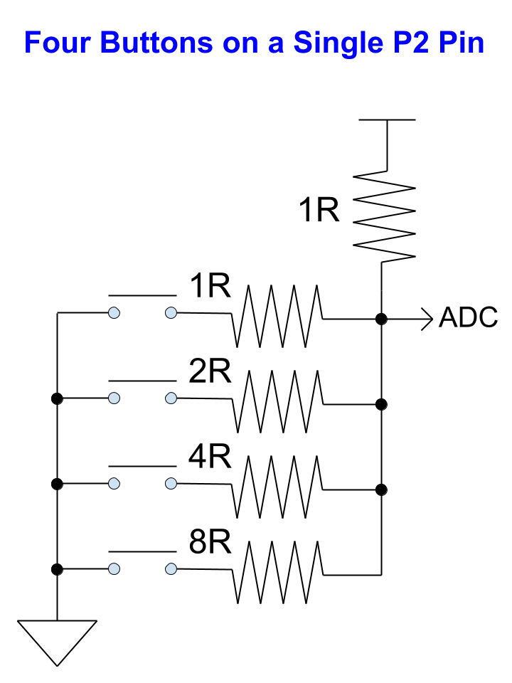
I hope you can see that.
Here's my board. I ganged 1K resistors to get the various values. You could get by with two SMT 4-pack resistors of R and 4R values, for practicality:
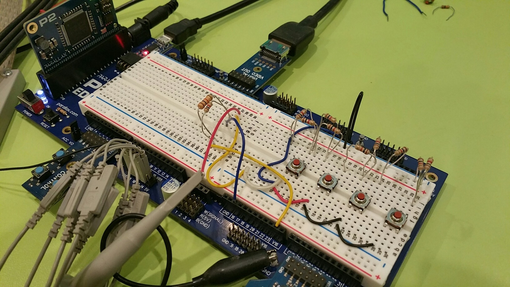
An ADC is used to read the states, which are non-linear:
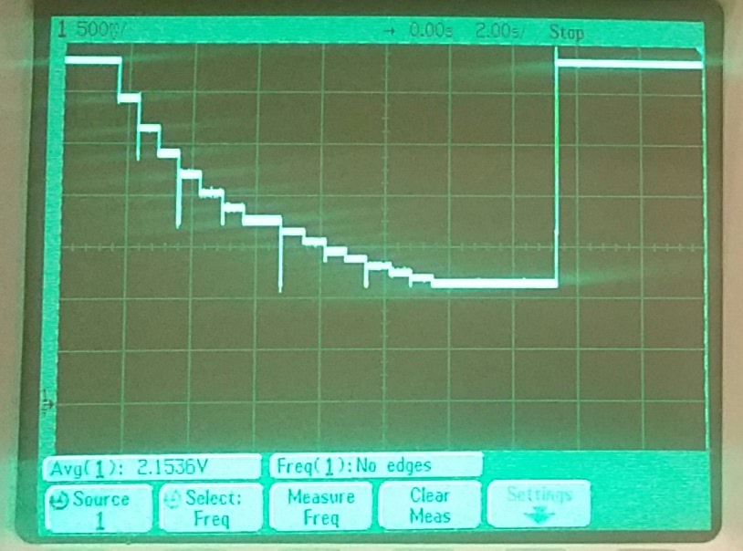
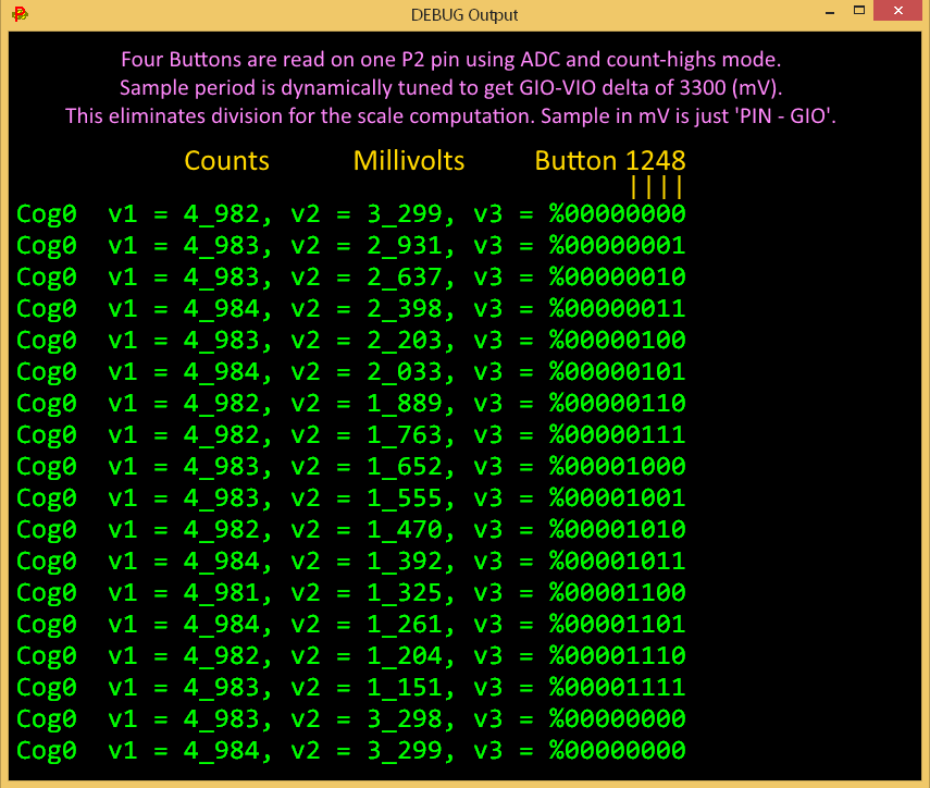
I didn't want to have the ADC need any complex scale+offset calibration, so I made an adaptive sampler that starts off in the ballpark and then homes in on the number of clocks that it takes to get a 'VIO minus GIO' delta of 3300, which results in direct millivolt readings for the 'PIN minus GIO'. Now we get good data without anything more than ADD/SUB. This would only work for one pin at a time, since each pin would need a slightly different number of clocks to get the VIO-GIO delta of 3300.
Here is some DEBUG data, as I cycled through all the pushbutton-press combinations:
And here is the code:


Comments
This is going to allow the 8080 arcade emulator to run each machine from:
8 arcade machines will be emulated over just 24 pins, with the P2 running at under 50MHz.
So you're saying there's no problems wherein it detects an intermediate state? (i.e. detecting a button as briefly pressed that never actually got pressed, but a state where it is lies between the two states being transitioned between)
It doesn't seem to do that, though I should add some debounce for each button channel. The whole sampling loop runs at 5 KHz.
That's a neat trick. Wonder if there's a choice of resistors that would give equal voltage steps...
I just googled a bit and there's a lot on Arduino doing this. But, seems they only work when 1 button is pushed at a time. This is better than what I've found so far...
It's a four bit dac, so one might use a r-2r ladder https://en.wikipedia.org/wiki/Resistor_ladder
I think this will work better and works for any combination of switches pressed
OOps too close! Need to adjust
How about this content being a P2 Quick Byte?
I realize by now that I'm broken, stuck in an endless loop:
P2 Quick Byte
P2 Quick Byte
P2 Quick Byte
Ken Gracey
Chip's scheme appear similar to the one here:
https://www.edn.com/read-multiple-switches-using-adc/
But, they got linear levels, looks like...
This R2R one might be good:
https://electronics.stackexchange.com/questions/247538/using-as-little-pins-as-possible-for-multiple-buttons
Using my above circuit, but with the fixed resistor being 15R I get these results. The smallest deviation is 0.057V. Looking at Chip's results the smallest deviation is 0.53V measured.
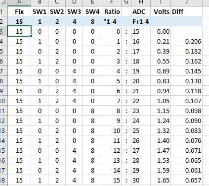
It's possible with tweeking the smallest deviation might be able to be increased a little.
try R2R. Lots of sources for this. My 2012(?) ADC/DAC post used a 12bit R2R network into an ECG opamp for the DAC side.
At least for me this would be a perfect P2 QB, amazing to learn something new every day from this forum
I simulated this R2R. Looks perfect! (except for little glitch at midrange...)
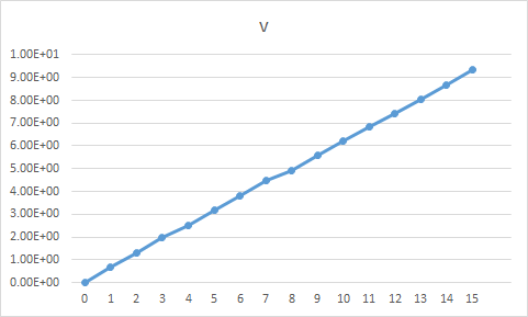
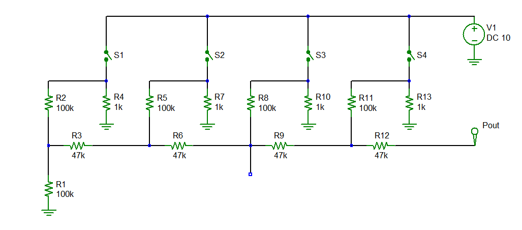
Thanks for working on this, Chip (and for perhaps updating it if another topology has advantages). With all the testing and so on, it was more involved than I realized when I mentioned it to Ken as a possible QB topic. I had presumed that it was just standard A2D stuff, even with detecting multiple buttons pressed at once (though there is often more than one way to skin a cat). But you appear to have nailed it (after adding de-bounce, if needed (need to do rapid-fire testing)). Also, it's great that this can be done with resistor pack(s), as like you said in the Zoom meeting, it needs to be reasonably simple in terms of resources, otherwise it's more trouble than it's worth. And it's cool that it can be applied to your "Octocade" demo. But what will you do with the leftover pins and other resources? It's an embarrassment of riches. Update: Nice linearity, Rayman.
That was interesting. They linearized it by increasing the load current, but thereby decreasing the voltage span. It all comes down to resolving the smallest voltage difference on the highest-resistor pin when all the other buttons are pressed.
Our limitation comes from the GIO and VIO calibration resistors inside our ADCs. There are separate 480k resistors for GIO, VIO, and PIN. I should have made one single 480k resistor with the selector switches in front of it. Mismatch would have been way lower and we would have had a more accurate idea of actual GIO and VIO levels. If we get to re-spin the chip, this is something I'm going to fix.
That looks good. It would take a few more resistors, but certainly be more linear. The problem with R-2R DACs is always the MSB transition point, where all the imperfections conspire, even creating a voltage step in the wrong direction if things are imperfect enough.
I guess R12 there isn't really needed...
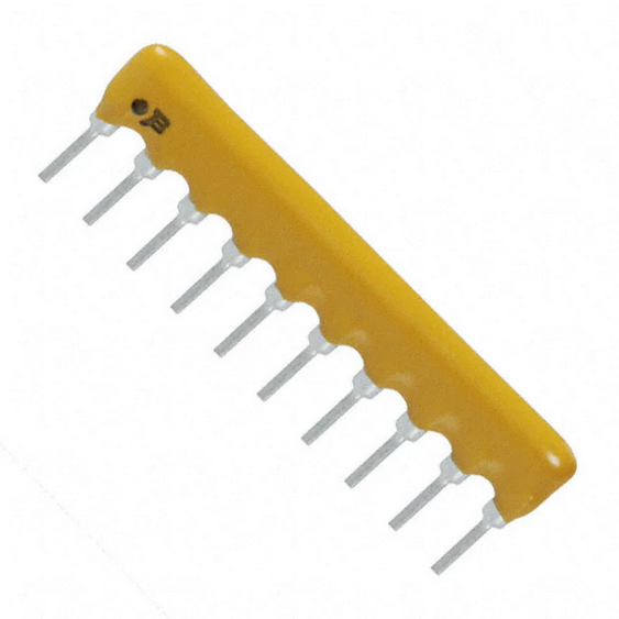
OMG - You realize they make R2R resistor series in a small SIP module right?! ... and the resistor values are all matched internally
Example: Digikey part number .... 4610X-R2R-103LF-ND
If you want it linear, use Capacitors instead of Resistors. They add up if you switch them in parallel.
Gee thats neat Ariba
I've respun our MicroPython sampler board that uses a related concept, i'll post in a separate thread
We'd need maybe one 16nf capacitor always connected so that it could have some reference frequency.
Do you want to try that out? I wonder how linear it would really be. Might be pretty good.
They seem hard to get and expensive these days. We used to use those on PIC pins to make fast DACs. They worked like magic.
https://www.digikey.com/en/products/filter/resistor-networks-arrays/50?s=N4IgjCBcoLQExVAYygFwE4FcCmAaEA9lANogCsIAuvgA6pQggC+T+CkpASnJ1U0A
This note appears to cover all this:
https://www.analog.com/media/ru/training-seminars/tutorials/MT-015.pdf
Using a variation of this idea you could read an entire matrix keypad with a single pin .
Here is something from the "Way-Back-Machine" on my old web sight.... I think you could get creative and do away with the 74HC14 and implement polarity switching from the I/O pin ... think 1-pin sigma delta ADC
Okay I've made a quick test with this circuit:
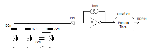
and this code:
CON
  _clkfreq  = 180_000_000
  BTNS = 28   'input pin

PUB testIt() | cv, idle, buttons
  pinstart(BTNS, P_SCHMITT_A_FB + P_HIGH_1MA + P_LOW_1MA + P_INVERT_OUTPUT + P_OE + P_PERIODS_TICKS, 1, 0)
  waitms(100)
  idle := rqpin(BTNS)                 'idle value (no button pressed)

  repeat
    waitms(100)
    cv := (cv + rqpin(BTNS)) / 2      'get average capacity
    buttons := (cv / idle) >> 1       'calc button bits
    debug(ubin(buttons))              'show as binary
A had no other caps that gave a 1:2:4:8 ratio, these valus are not so optimal. But it works well, I see the bit pattern changes with the buttons, every button corresponds to one bit.
If I look at the raw value, the button with the 100nF C gives 9 times the idle value, (100nF / 11nF), so the capacity measurement seems to be quite linear.
For 4 buttons the cap ratio needs to be more precise, and I would use smaller Cs.
Andy
That's great, Andy. Maybe it could even handle another button, or two. Thanks for trying that. I like where you put the always-connected cap.
The caps do need to be big enough to swamp out any parasitics.
What was the idle count?
That's pretty wild, Beau. I can't figure out the principle of operation, other than the Stamp would do a PULSIN. Is this alien technology?
The keypad in combo with the 74HC14 modulates both halves of the PWM signal to the I/O pin. The "ROWS" modulate the top width of the PWM, while the "COLUMNS" modulate the bottom width of the PWM.
The idle count is around 4000. For sure you can make it higher with 100uA feedback instead of 1mA.
That's really ingenious. So, you would measure the high pulse and the low pulse to get the key being pressed.