

Anomaly Found with LED Matrix Test Tool
 CJMJ
Posts: 226
CJMJ
Posts: 226
in Propeller 2
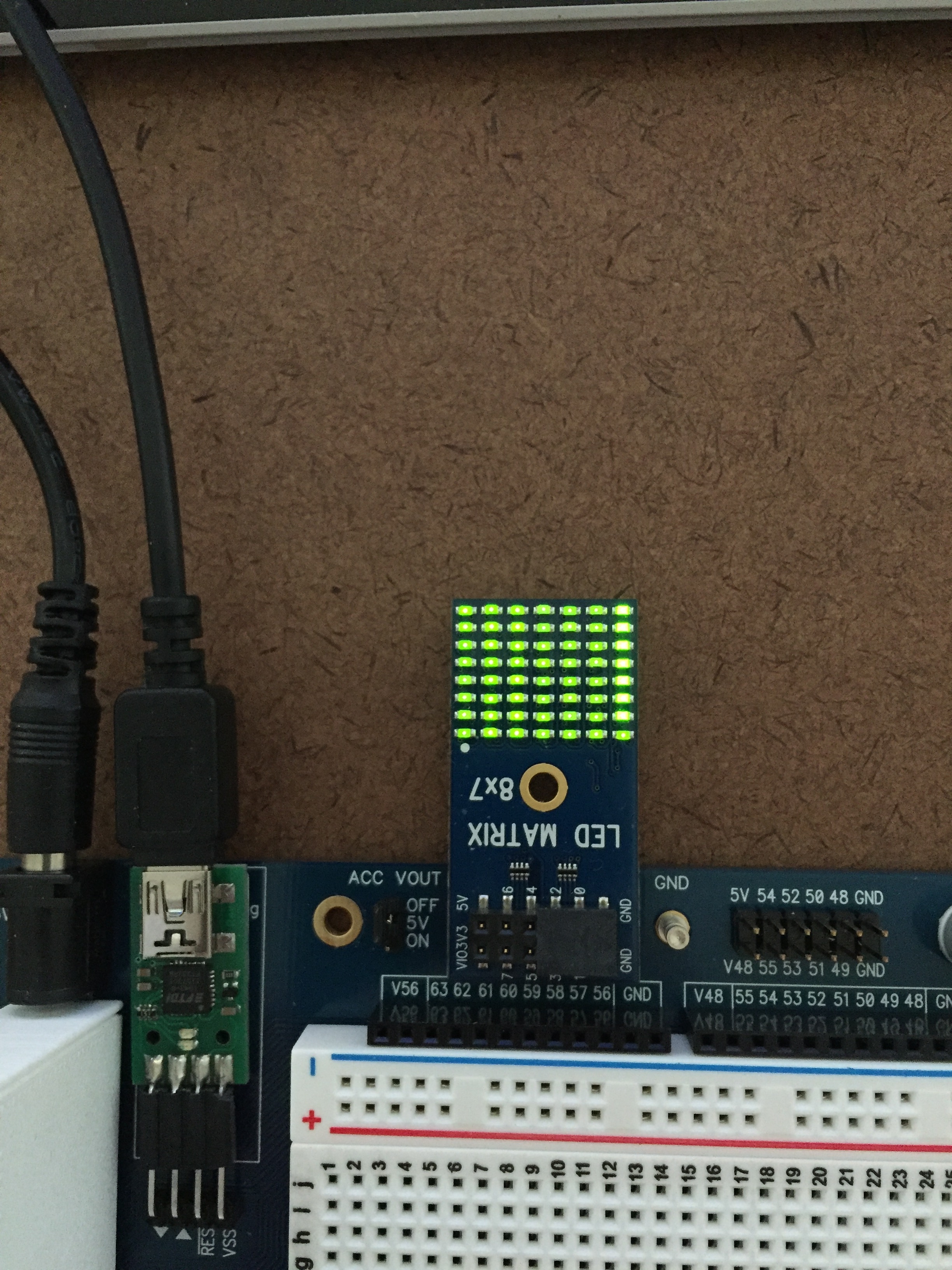
While testing my Quick Byte app on the P2 Edge Module Breadboard and the P2 Edge Mini Breakout Board I noticed P63 was running a little hotter than the other pins (see image). I don't see this on the Propeller 2 Evaluation Board (Rev C).
Any comments?
Any comments?
2448 x 3264 - 2M
Comments
FWIW, I treat pins 56..63 as off-limits for external hardware for P2 Eval and Edge projects.
The pins shown below have a special purpose upon power-up/reset but are
general purpose I/O afterwards
Here the P1 manual was referring to P28-P31. The P2 manual is far from complete but I'm assuming that the same functionality would apply to the P2 special pins as well.
Here I'm just testing the pins well after the power-up/reset period is over. Also, I only see this anomaly with the P2 Edge. As I noted the Rev C Evaluation Board results are as expected.
Normally, I would avoid these pins since I have plenty to work with, however, if they are going to function differently than the P1 special pins, this needs to added to the P2 documentation to NOT use these pins.
Bottom line is I'm just trying to understand how the P63 on the P2 Edge differs from the Eval Board. A difference in the pull-up value or circuit may be the answer. I'll take a look at that. I'm wondering if there's any other performance differences in the P63 RX pin on the Edge.
While out running an errand it dawned on me that you're using nested loops. The last LED in each inner loop is going to get a little more time that the others because the code branches back to the outer loop. Unfortunately, I have misplaced my matrix board, so I can't test this theory. Here's what I suggest. Using waitct() and minimizing the time between clearing the LED and turning one back on should give you better brightness, and more consistent output.
  pinfield := basepin addpins 7

  t := cnt
  repeat
    repeat offset from 0 to 55
      hipin := basepin + lut[offset].[%00011_00100]
      lopin := basepin + lut[offset].[%00011_00000]
      pinf(pinfield)
      pinh(hipin)
      pinl(lopin)
      waitct(t += ON_DELAY)
You'll need to determine the value of ON_DELAY for your clock speed. I also suggest you don't re-calculate the pin field inside the loop -- this never changes during the loop, so re-calculating is just using extra time.My matrix board driver (attached) uses waitct() for the delay between pixels.
That said, I stand by my other suggestions.
Your right about the PINF(basepin ADDPINS 7) call within the loop. It didn't occur to me at the time this was a calculation. Don't ask me what I thought it was. Probably thought it was a setting. Once my brain gets stuck on a thought I need someone to shake it free. Thanks.
Just setup the mini board and its performing just like my code. The LEDs powered by P63 is still a little brighter than the rest.
Just saw your additional comments and those by @Tubular and I agree. The prop plug is the difference. I didn't realize how it worked after the power-up/reset phase.
Oh, just to confirm. While testing the latest version of my code on the mini breakout board at basepin 56, P63 reduced in brightness to the same level as the rest of the pins when I switched off the Prop Plug at the USB hub. Therefore the Prop Plug or more correctly the FTDI chip is causing a little higher voltage on the RX pin. I have different versions of the Prop Plug so my next experiment will be to check which FTDI chips they and the eval board are using. This was fun.
I'm am still of the opinion that pins 56..63 should not be used as general purpose IO. Yes, I know what the manual says, but the manual also says that these pins are used for programming, debugging, and storage. I have found that the buffers on 56 and 57 do not play nicely with all circuits (e.g., I2C), hence they are on my "don't connect anything to these" list for the Edge and the P2 Eval (a custom board would be a different story).
Suggestion: It actually took me a second to see what was happening with these lines:
      hipin := BASE_PIN + LUT[offset].[%00011_00100]            ' bitfield for upper 4 bits
      lopin := BASE_PIN + LUT[offset].[%00011_00000]            ' bitfield for lower 4 bits
Those lines could be written like this, which I believe adds clarity to the program. The compiled result is the same.hipin := BASE_PIN + LUT[offset].[7..4] ' bitfield for upper 4 bits lopin := BASE_PIN + LUT[offset].[3..0] ' bitfield for lower 4 bitsI'm a very visual person so I dropped your code into my template using my style guidelines so that I could study it without visual distractions. I'm highly sensitive to code that doesn't use much white space. It's attached in case you're interested.
The P2 has instructions that let you pluck a nibble out of a table, hence my offset in this code goes from 0 to 111. The incmod instruction is useful, too, as in helps us with an automatic roll-over to 0 after reading the last nibble in the table.
pri main2(base, tix) | pinfield, offset, t, hipin, lopin        ' runs forever!

  org
                mov       pinfield, #7                          ' create pin field for 8 pins
                shl       pinfield, #6
                or        pinfield, base

                mov       offset, #0                            ' initialize offset
                getct     t                                     ' initialize led timer

.loop           altgn     offset, #.lut                         ' point to low pin
                getnib    lopin                                 ' read it
                add       lopin, base                           ' adjust for base pin
                add       offset, #1                            ' bump to high pin for this led
                altgn     offset, #.lut                         ' point to high pin
                getnib    hipin                                 ' read it
                add       hipin, base                           ' adjust for base pin
                incmod    offset, #111                          ' increment with rollover
                fltl      pinfield                              ' clear last led
                drvl      lopin                                 ' light current led
                drvh      hipin
                addct1    t, tix                                ' update timer
                waitct1                                         ' let it expire
                jmp       #.loop


.lut            byte      $01, $02, $03, $04, $05, $06, $07, $10
                byte      $12, $13, $14, $15, $16, $17, $20, $21
                byte      $23, $24, $25, $26, $27, $30, $31, $32
                byte      $34, $35, $36, $37, $40, $41, $42, $43
                byte      $45, $46, $47, $50, $51, $52, $53, $54
                byte      $56, $57, $60, $61, $62, $63, $64, $65
                byte      $67, $70, $71, $72, $73, $74, $75, $76

  end
A few minutes later... I wondered if using bytes and extracting the pins would use more or less code. It doesn't -- the same number of lines are used. This is the byte-oriented loop:
.loop altgb offset, #.lut ' point to led pins getbyte lopin ' read them mov hipin, lopin ' copy and lopin, #$0F ' isolate low add lopin, base ' adjust for base pin shr hipin, #4 ' isolate high add hipin, base ' adjust for base pin fltl pinfield ' clear last led drvl lopin ' light current led drvh hipin addct1 t, tix ' update timer waitct1 ' let it expire incmod offset, #55 ' increment with rollover jmp #.loopThe PASM2 code is nice and compact. That, also, would make a good Quick Byte on how to do the same think in PASM2 for someone trying to understand PASM2.
I'm updating my style guidelines for publication -- will attach those when done.
I'm having a lot of fun learning assembly on the P2. One of the bigger projects I have coming up is the P2 version of P1 laser-tag system I coded a few years ago. I want to use as much of the P2 horsepower as I can muster.