Shop OBEX P1 Docs P2 Docs Learn Events
Porting a P1 object to P2 - Issues with SPI — Parallax Forums

Porting a P1 object to P2 - Issues with SPI

Greg LaPollaGreg LaPolla Posts: 320
edited 2020-12-02 00:26 in Propeller 2
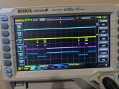
Below are my read and write routines converted from spin to spin 2. I can see activity on my oscilloscope but I cannot decode spi. I don't quite have a grasp on the smart pins yet. Is there anything obviously wrong ?
pri read(): Value

  dira[dout]~                                                 ' make dout input
  outa[sclk] := ClockState                              ' set initial clock state
  dira[sclk]~~                                                ' make clk output
  Value~                                                        ' clear output

  repeat Bits
    pintoggle(sclk)
    waitct(getct() + ClockDelay)
    pintoggle(sclk)
    waitct(getct() + ClockDelay)
    Value := (Value << 1) | ina[dout]

  return Value
pri write(Value)

  dira[din]~~                                                   ' make Data pin output
  outa[sclk] := ClockState                                      ' set initial clock state
  dira[sclk]~~                                                  ' make Clock pin output
  Value <<= (32 - Bits)                                         ' pre-align msb

  repeat Bits
    outa[din] := (Value ROL 1) & 1                              ' output data bit
    waitct(getct() + ClockDelay)
    pintoggle(sclk)
    waitct(getct() + ClockDelay)
    pintoggle(sclk)

Read seems to work (PINK) but write doesnt do anything (TEAL). Yellow is clock and blue is Chip Select
770 x 578 - 136K

Comments

  • Is your original code all Spin1? If so you could try compiling it with FlexProp, which can compile Spin 1 for P2 (and also Spin2). Eventually you'll probably want to port to Spin2 to share it, but with FlexProp you can do this in steps.
  • This stuff is much simpler with the P2:

    Suggestions:
    -- don't use dira[], outa[], ina[], etc; P2 pinxxx instructions handle all that
    -- don't use post set and clear operators; they're slower than direct assignments
    -- you probably don't need to slow the clock bit

    Try this:
    pri read(bits) : value
    
      pinclear(DIO)                                         ' make input (clear SP mode)
      pinwrite(SCLK, IDLE_SCLK)                             ' set SCLK to output and idle
    
      repeat bits
        pintoggle(SCLK)                                     ' clock the bit
        waitus(1)
        pintoggle(SCLK)
        waitus(1)
        value := (value << 1) | pinread(DIO)                ' read new bit (MSBFIRST)
    
    
    pri write(value, bits)
    
      pinwrite(SCLK, IDLE_SCLK)                             ' set SCLK to output and idle
    
      value << 32-bits                                      ' move msb to value.[31]
    
      repeat bits
        pinwrite(DIO, value rol= 1)                         ' write bit to DIO
        pintoggle(SCLK)                                     ' clock the bit
        waitus(1)
        pintoggle(SCLK)
        waitus(1)
    
  • @JonnyMac Thanks for the response. Working through this what would the value of IDLE_SCLK be ?
  • Peter JakackiPeter Jakacki Posts: 10,193
    edited 2020-12-02 00:02
    This is the SPI read routine in PASM that I've used in TAQOZ from day one that takes into account the delay in reading an input. It is very unlikely that you need to slow anything down although having a longer clock pulse (using a nop or two) improves the shape at higher speeds. I find that bitbashed SPI bus runs at about 1/10 of the system clock, so 20MHz for a 200MHz clock. This means unless it is a slow device or you have long leads etc, then there is no need to add delays.

    BTW, I use different but similar routines for block SPI that reads and writes blocks in memory.
    SPIRD            rep     @sre1,#8                ' 8 bits
                     outnot  sck                    ' clock (low high)
                     nop                            ' stretch out the clock 
                     outnot  sck
    RWAIT		 nop                            ' delay needed until pin registers data
    		 nop
                     testp   miso wc                ' read data from card
                     rcl     a,#1                   ' shift in msb first
    sre1            ret
    
    SPITX8		rep     @.L1,r1
    		 rol     X,#1 wc		' output next msb
            	 drvc    mosi			'  xDDDxDDDx'
                     drvnot  sck			' ---C---C--
                     nop
                     drvnot  sck			'
    .L1		ret
    
  • BTW You can do bitfield operations in Spin2 by using "." in between variable and bit reference.
        outa.[din] := Value rol= 1                   
    
  • @JonnyMac Thanks for the response. Working through this what would the value of IDLE_SCLK be ?
    It would be 0 or 1 -- whatever the idle state of your clock line is to be.
  • As a learning point for me... This writes only the MSB bit to the pin?
    JonnyMac wrote: »
    pinwrite(DIO, value rol= 1) ' write bit to DIO

    From the flexspin docs (yes, may be different from PNut Spin2...):
    _PINW
    _pinw(p, c) forces p to be an output and sets it to 0 if c is 0 or 1 if c is 1. If c is any other value the result is undefined. Supported for both P1 and P2
    

    Just trying to understand!

    Thx
    dgately

  • JonnyMacJonnyMac Posts: 9,104
    edited 2020-12-02 01:11
    Yes. The rol= instruction rotates the value left (and reassigns it to the rotated value), so bit31 ends up in bit0, and then bit0 is written to the pin (assuming DIO is one pin, not a pin group).
  • @JonnyMac Thanks! I figured as much. The timing is off a little. I have a 2 channel Thermocouple Controller ADS1118. I can read the first channel no problem, but switching to the second one I get some weirdness. I have to pull the spec sheet and get the timing params.
  • dgatelydgately Posts: 1,630
    edited 2020-12-02 01:41
    JonnyMac wrote: »
    Yes. The rol= instruction rotates the value left (and reassigns it to the rotated value), so bit31 ends up in bit0, and then bit0 is written to the pin (assuming DIO is one pin, not a pin group).
    Ah... Oh yes, ROL not shift left!


    But...

    I think you meant:
    not this:
      value << 32-bits                                      ' move msb to value.[31]
    but, this?:
      value <<= 32-bits                                      ' move msb to value.[31]
    

    THx!

  • JonnyMacJonnyMac Posts: 9,104
    edited 2020-12-02 01:39
    Since you want to control the speed, you can use code similar to Peter's and embed it into Spin2 methods.
    pri read(sclk, din, bits, khz) : value | tix
    
      tix := clkfreq / (khz * 1000) >> 2                            ' 1/4 clock time
    
      org
                    drvl      sclk                                  ' sclk is output/low  
                    fltl      din                                   ' make din input
    
                    rep       #8, bits
                     waitx    tix
                     drvh     sclk
                     waitx    tix
                     waitx    tix
                     drvl     sclk
                     waitx    tix
                     testp    din                           wc      ' sample din
                     rcl      value, #1                             ' shift into result
                     
                    ret
      end
    
    
    pri write(value, sclk, dout, bits, khz) | tix
    
      tix := clkfreq / (khz * 1000) >> 2                            ' 1/4 clock time
    
      org
                    drvl      sclk                                  ' sclk is output/low
                     
                    ror       value, bits                           ' move msb to bit 31
                    
                    rep       #8, bits
                     rol      value, #1                     wc      ' get bit
                     drvc     dout                                  ' write to dout
                     waitx    tix                                   ' let dout settle
                     drvh     sclk                                  ' clock high
                     waitx    tix
                     waitx    tix
                     drvl     sclk                                  ' clock low
                     waitx    tix
    
                    ret
      end
    
    This assumes clock idle state is low (I looked at the data sheet for that device)
  • Thanks for the help!

    I got it working. For some reason though I still cant decode it on my scope.
  • Just a reminder: The P2 handles pin #s differently, so using code like this
      if (ina[dout] == 1)
        repeat
        until (ina[dout] == 0)
      else
        waitct(mark)
    
    ...can lead to unexpected troubles if the pin is > 31. Better to use this form:
      if (pinread(dout))
        repeat
        while (pinread(dout))
      else
        waitct(mark)
    

    Suggestions:

    In your start() method, change...
      ClockState := _ClockState
    
    to:
      pinlow(sclk)                                          ' set sclk idle to output/low
    

    If you change the BITS constant to a parameter in read() and write() like this
    pri read(bits) : value
    
      pinclear(dout)                                        ' make dout input
    
      repeat bits
        pinhigh(sclk)
        waitus(1)
        pinlow(sclk)
        waitus(1)
        value := (value << 1) | pinread(dout)
    
    
    pri write(value, bits)
    
      value ror= bits                                       ' pre-align msb
    
      repeat bits
        pinwrite(din, value rol= 1)                         ' output data bit
        pinhigh(sclk) 
        waitus(1)     
        pinlow(sclk)  
        waitus(1)
    
    ... then bits like this:
      pinl(cs)
      write(cmode.byte[1])
      write(cmode.byte[0])
      pinh(cs)
    
    ...become:
      pinl(cs)
      write(cmode, 16)
      pinh(cs)
    
    ...and...
    pri sample() : result | mark
    
      mark := (clkfreq >> wsps) * 5 / 4 + getct()
    
      pinl(cs)
    
      if (pinread(dout))
        repeat
        while (pinread(dout))
      else
        waitct(mark)
        
      result := read(16)
    
      pinh(cs)
    

    Finally, using...
      return result
    
    ...is redundant -- unless you're modifying the return value in the last step, like this:
      return result >> 1
    
  • JonnyMacJonnyMac Posts: 9,104
    edited 2020-12-03 01:14
    While listening to the P2 meeting I connected my logic analyzer. Here's a version of write()
    pri write(value, bits)
    
      value ror= bits                                       ' move msb to value.[31]
    
      repeat bits
        pinwrite(DOUT, value rol= 1)                        ' write bit to DOUT
        pintoggle(SCLK)                                     ' clock the bit
        waitus(1)
        pintoggle(SCLK)
        waitus(1)
    
    I ran a simple test loop:
      repeat
        pinl(CS)
        write($A5FF, 16)
        pinh(CS)
        waitms(50)
    
    I've attached the capture from my $13 logic analyzer running through PulseView with the SPI decoder enabled.
    989 x 499 - 40K
  • I can see the config string being sent.

    Weird my scope cant see it.
Sign In or Register to comment.