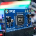
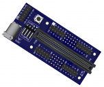
P2 Edge Mini Breakout Board - Schematic and Pictures
 Ken Gracey
Posts: 7,419
in Propeller 2
From the P2 Live Forum yesterday, you asked for more design details around this breakout board.
These are all attached. We won't be able to answer questions about this right now; we're too focused on getting all these products through our manufacturing and for sale.
Thanks,
Ken Gracey
These are all attached. We won't be able to answer questions about this right now; we're too focused on getting all these products through our manufacturing and for sale.
Thanks,
Ken Gracey


Comments
This could be useful layout or breakout for the P1, if the P1 were to go to the edge concept.
Ray
It might be possible to at least make it electrically okay to reverse even if not runable that way. The alternative is add keying, preferably as external to the connector so that the 80 contacts are retained.
1..37 P2_IO0-P2_IO36
38 GND
39 GND
40 5V
41..75 P2_IO37-P2_IO63 plus VIOx8
76 P2_RESN
77 NC
78 GND
79 GND
80 5V
As stated abov, by JRetSapDoog, P2 Edge targets includes the educational market, so, by making use of such a circuit would suggest new opportunities for further learning.
IMHO, "Why it don't burns, when connected backwards?" could be one of the many possibilities, for such kind of insightfull questions, usually asked by knowledge-hungry minds.
Edge Module has the reverse voltage protection built in, and the pin out is set so that accidental use of the P2 Edge module in classroom microbit accessories, or accidental reversal, will cause no harm.
The mini breakout pcb has pins P0 and P38 labelled at the 80way edge connector, to guide module insertion.
Also for Ray, the maxi breakout will be another product #64020. Due in store first half of November, along with the Edge module, an 80pin adapter kit #64018 and this mini breakout #64019.
Thank you VonSzarvas for the clarification, and also to rogloh, by having spoted such possibility, thus providing another chance, for improving the general community knowledge-base.
too?
Is there any Kicad patterns available?
Bill M.
Yes, both versions: vertical and right-angle. We'll post the DipTrace layouts when the parts are posted, in about two weeks.
Ken Gracey
I don't know if Parallax or other people have considered the possibility
of mixing Micro:Bit 80 pin and 40 pin connectors on the same P2 board
Bill M.
I'm certainly working on one board that can do these
* 40 pin "P2DIP40", using P1 footprint
* 80 pin "P2DIL80", using two 40 pin stackthrough headers
* 20 pin "P2SIP20", using a single right angle header
I'm also making a mating breakout pcb that breaks these, or Parallax's P2 Edge, to Mikrobus/Pmod/Servo/Arduino/Parallax accessory headers
I'll post some photos later this week
About those connectors...
The physical size and pinout of the connectors used by micro:bit and P2 Edge are the same. They are 80 way 1.27mm pitch card edge connectors.
Commonly available in Straight (Vertical) or right-angle styles, through-hole or SMT.
The connectors allow for 80 pins in total (40 connections top, 40 connections bottom).
P2 Edge uses both sides of the PCB edge connector, so all 80 pins.
micro:bit only uses the top side of the PCB edge "connector" for connections, so only 40 pins. The bottom side pins on a micro:bit PCB are not connected to anything (apart from the large croc-clip holes, which are plated through).
To add some additional options.... some enterprising manufacturers are now marketing 40 pin versions of the connector too! They are essentially 80 pin sockets with the bottom row of pins removed! (to save costs I suppose!). They still accept both micro:bit and P2 Edge as the slot is the same size as the 80 way, but as they only make connection to the 40 pins on the top side of the PCB. Ie. They are fine for micro:bit, but not ideal for P2 Edge!
In a nutshell-
The 80 pin sockets (double sided, 40 pins top and bottom) are compatible with both P2 Edge and micro:bit boards.
The 40 pin sockets (single sided, 40 pins top) for micro:bit only.
As Ken mentioned, Parallax will be stocking the 80 pin Through-Hole sockets, in both Straight and Right-Angle versions.
The footprint patterns are slightly different for the two versions- datasheets, Diptrace and gerber files will be available.
searching for connectors found that there were many hi priced edge
connectors.
So, with no experience with building a large pin project, I have been
trying to find reasonable priced alternatives for building a 1/2 pcb
and 1/2 breadboard for prototyping my P2 projects.
I didn't know if Parallax stocked the 40 pin connector.
A Micro:Bit 40 pin connector could be used in conjunction with the 80 pin
connector to hold a pcb that is filled with parts that I don't want to use a
bread board for.
I am not trying to suggest a new product. Instead I was trying to find out
if Parallax was a source for the 40 pin connectors.
Bill M.
Originally the 40 pin options I found on the Micro:bit site didn't
pan out. But I have since found a couple of other sources.
Jon, I took Ken's comments and interpreted that as:
80 pin (std P2 edge connector) vertical, and right angle.
And then VonSzarvas confirmed it.
IMO the 40 pin was useful for other P1/P2 applications.
Anyway, I wanted to draw up the 80-pin connector in DipTrace, but I was unsure of the spacing between the four rows of pins. I had difficulty finding a drawing for the connector online, but I finally located one that I hope is applicable. And it shows the spacing between the four rows as being 1.9 mm (or 1.9 mm x 3 for the three gaps between the rows), so that's what I used. Hope it's right. {Update: that's for the right-angle connector; see update below} That drawing does mark Pin 1, but I'm still a bit unsure about the pinout. At any rate, here's the PDF for the (right angle) connector I mentioned.
As for the patterns being "slightly different," I wonder how different they are. Will a straight connector physically fit in the pattern for the right-angle one, and vice-versa, I wonder. I'd hope so. {Update: No, the row-spacings are different; see update below} And if so, is the electrical pinout the same? Again, I would hope so but don't know so. Perhaps the "slightly different" wording refers only to the silkscreen markings, as the pattern for the right-angle connector likely shows the overhang of the connector above the board (traces could run there but the overhang could interfere with locating components there).
Update: Although I don't have the connectors in hand yet from Parallax, it appears that the straight connector has a 0.1" row spacing, while the right-angle connector has a 0.75" (1.9 mm) row spacing.