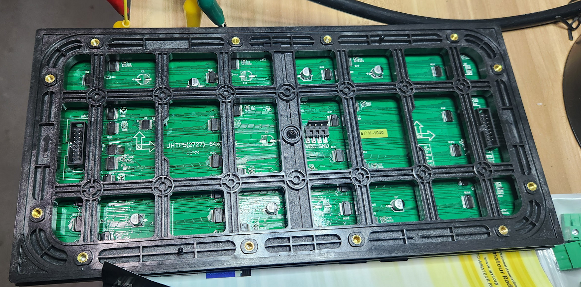
I picked up one of the HUB75 adapters from Parallax and bought 4 panels from a vendor that I get Christmas light accessories from. These P5 panels are nebulas as to their specifications and chip is driving them.
I am having some issues with setting proper geometry for these panels. These appear to be 64x32 1/8s Model Number is jhtp5P5(2727)-64x32-8s
I get a pulse with PANEL_DRIVER_CHIP = CHIP_GS6238S However, if you look at the images below, it looks like I am getting some kind of weird double scan going on. These are from the text demo.
Any help would be appreciated. I have no idea what I am doing.
    ADAPTER_BASE_PIN = PINS_P32_P47
   ' (1) determine what form of signalling the driver should use
    PANEL_DRIVER_CHIP = CHIP_GS6238S 'CHIP_ICN2037'CHIP_GS6238S 'CHIP_UNKNOWN  ' CHIP_UNKNOWN

    ' (2) describe the panel electrical layout
    MAX_PANEL_COLUMNS = 64
    MAX_PANEL_ROWS = 32
    PANEL_ADDR_LINES = ADDR_ABCD

    ' (3) describe the organization of panel(s)
    ' panels organization: visual layout
    '   [1]      1 row of 1 panel
    '
    ' (4) describe the organization in numbers of panels
    MAX_PANELS_PER_ROW = 1
    MAX_PANELS_PER_COLUMN = 1

    ' (5) describe the color depth you want to support [3-8] bits per LED
    '    NOTE full 24bit color is DEPTH_8BIT
    COLOR_DEPTH = DEPTH_8BIT
Can you see the ICs on the back of the panels? If you can, please respond with a hi-res pic of one of them. I should be able to learn more by looking at how the ICs are laid out and what the chip numbers are.
My Driver Software page shows the various ICs we already know of. It also describes settings we can fiddle with.
Please end the pics, let's go from there...
Also, are you planning on making these into one display? And do the panels each have in and out HUB75 connectors?
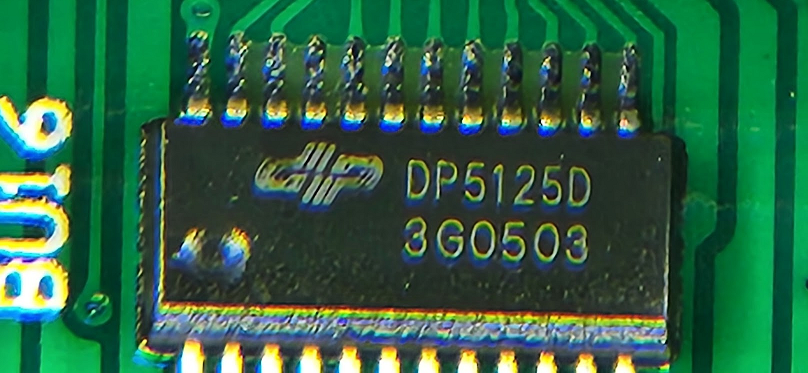
@"Stephen Moraco" Here are the ICs on the board: DP5125D No datasheet is available that I can find. Apparently there are two variants, the "D" like I have, which is outdoor rated and the "T' which is not.
They are laid out in row like this:
6-4-----------6-4------------6-4-----------6-4
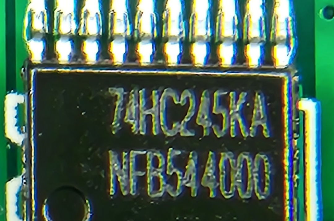
40 in total + what appear to be line driver ICs.
My plan was to use 4 of these to make a 64x128 display.
Yes, it shows the HUB75 connector pinout. Like many of them, it has typos, LOL. I have no idea how the Chinese get anything done with no datasheets and typos all over everything.
DP5125D QSOP24 LED driver chip 16 bit Developer Microelectronics Original new goods
DP5125D is a low power consumption green intelligent constant current perfusion driver chip specially designed for LED display, integrating black screen energy-saving technology and control system adaptive technology. The chip power on intelligently identifies the working mode, and is compatible with and expands the existing common single latch constant current chip and double latch constant current column under blanking chip in the market.
◆ 16 bit constant current perfusion current output, constant current output range:
2mA~ 40mAVDD =5V
2mA~ 25mA VDD = 3.3V
◆ Current accuracy:
Between channels:+1.0% (typ.)+2.5% 6 (max)
Between chips:+1.0% (normal value)+2.5% (maximum value)
◆ Low power consumption, green energy saving and extremely low static power consumption
◆ Black screen energy saving, single chip power supply current under black screen mode is lower than 0.2mA
◆ Adaptive technology of control system:
General program: single latch without blanking (it can support single, dual color and full-color applications, without blanking function, and will not cause lamp bead back pressure) Double latch program: double latch with blanking (it supports double latch full color screen applications with blanking requirements, and the refresh rate is more than 50% higher than the general constant current chip)
◆ Integrated chip anti burning protection circuit, no PCB burning, no open fire
◆ Working voltage range: 3.3V~5.5V
◆ Fast output current response (minimum): 40ns VDD=5V
Getting these panels working with a new chip is just "fun" so to speak.
The boundaries ahead of you are:
1. Getting the signals correct (driver settings)
2. Getting the colors correct (driver settings)
3. Getting multi-panel working (as one long chain)
4. Getting the muli-panel specification correct to match your layout
5. Enjoy your working display and let's find more to do with it!
If the chip vendors continue to use techniques I've identified so far, then getting this all correct is just a matter of selecting the needed options.
However, where it's going to get fun is when they finally branch out, and we need to implement new signaling. That's when the data sheets and test hardware for me to use come into play. I always hope we don't have to go this far... ;-)
Let's see if we can make the existing driver setting work for this new chip you've found.
Ok, I've studied the code a bit and added a new section to the docs: Chip ID expands to...
You are using the CHIP_GS6238S, which is mostly working.
According to this new table, this expands to CHIP_MANUAL_SPEC, LAT_POSN_OVERLAP, LAT_STYLE_OFFSET, and GB_SWAP.
Once the panel signaling is correct, we will determine if GB_SWAP (or RB_SWAP or no swap) is needed. There's a specific demo you run to help you determine this, allowing you to match the color swatch to the color name. (demo_hub75_colorPad.spin2) Take out the GB_SWAP, run the test. It should be obvious if two colors need to be swapped. If they do add back in the appropriate color swap option, the color issue should be corrected.
Since there is an indication that this is a ⅛ scan panel, you should first try adding SCAN_4 into this mix of options. See if that clears up the display.
(You should be able to replace the CHIP_GS6238S enum value with an or'd collection of these options)
After you have settled on your driver options/settings, I'll add this new chip to the code base with the options you found to work.
Your desired 4-panel arrangement is shown in Configuring the driver as you can see the panels are a single long serial chain. There is just more cable distance between the 2nd and 3rd panels, allowing you to break the chain into two rows.
I notided something else in your config which doesn't seem to match the legend in one of your pics. We'll want to keep this in mind in case it needs to be changed.
@Rayman is this what you were alluding to with your "abc" comment?
PANEL_ADDR_LINES = ADDR_ABCD I'm not sure if you want the D in here (maybe want ADDR_ABC?)
Also, when you finally get to mounting your panel-set then the driver also supports rotation: ROT_LEFT_90, ROT_RIGHT_90, ROT_180
(yeah, even after I answer my head keeps working on it... ;-)
Yeah, when I was looking on Ebay for panels, I noticed a lot of them are incorrectly identified regarding scan type.
But, when you look at the silkscreen and see "ABC", I think you can be pretty sure 1/8 scan and if see "ABCD" then 1/16 scan.
I'm thinking 1/8 scan is better, but haven't thought about that too much...
I've just released v3.0.1 of RGB LED Matrix Driver. The changes are:
**Add Chip's dithered fonts and add DP5125D IC support
Add support for panels using DP5125D chips
Add Chips' 5x7 dithered fonts
ICN2037_B was renamed to ICN2038S
MBI5124_8S was renamed to MBI5124GP
Rearranged user configurable files to improve compilation under Pnut/Propeller Tool - This allows us to support many more total pixels (now 64k) in a display.
If you find some issue with this code then please report it at my GitHub repository issues page. Otherwise, let's continue discussing in this thread! ;-)
Hmm, is there headroom to perform temporal dithering between frames? That could probably buy you two extra effective bits for still images without excessive flicker.
Comments
I picked up one of the HUB75 adapters from Parallax and bought 4 panels from a vendor that I get Christmas light accessories from. These P5 panels are nebulas as to their specifications and chip is driving them.
I am having some issues with setting proper geometry for these panels. These appear to be 64x32 1/8s Model Number is jhtp5P5(2727)-64x32-8s
I get a pulse with PANEL_DRIVER_CHIP = CHIP_GS6238S However, if you look at the images below, it looks like I am getting some kind of weird double scan going on. These are from the text demo.
Any help would be appreciated. I have no idea what I am doing.
ADAPTER_BASE_PIN = PINS_P32_P47 ' (1) determine what form of signalling the driver should use PANEL_DRIVER_CHIP = CHIP_GS6238S 'CHIP_ICN2037'CHIP_GS6238S 'CHIP_UNKNOWN ' CHIP_UNKNOWN ' (2) describe the panel electrical layout MAX_PANEL_COLUMNS = 64 MAX_PANEL_ROWS = 32 PANEL_ADDR_LINES = ADDR_ABCD ' (3) describe the organization of panel(s) ' panels organization: visual layout ' [1] 1 row of 1 panel ' ' (4) describe the organization in numbers of panels MAX_PANELS_PER_ROW = 1 MAX_PANELS_PER_COLUMN = 1 ' (5) describe the color depth you want to support [3-8] bits per LED ' NOTE full 24bit color is DEPTH_8BIT COLOR_DEPTH = DEPTH_8BITOk, that's an amazing start, good work!
Can you see the ICs on the back of the panels? If you can, please respond with a hi-res pic of one of them. I should be able to learn more by looking at how the ICs are laid out and what the chip numbers are.
My Driver Software page shows the various ICs we already know of. It also describes settings we can fiddle with.
Please end the pics, let's go from there...
Also, are you planning on making these into one display? And do the panels each have in and out HUB75 connectors?
@"Stephen Moraco" Here are the ICs on the board: DP5125D No datasheet is available that I can find. Apparently there are two variants, the "D" like I have, which is outdoor rated and the "T' which is not.

They are laid out in row like this:
6-4-----------6-4------------6-4-----------6-4
40 in total + what appear to be line driver ICs.


My plan was to use 4 of these to make a 64x128 display.
Thanks for all your help Stephen!
Wait, there are more hidden at the top and bottom........
12 per row. Looks like 4 drive red, 4 drive green, 4 drive, blue based on their part number RU1 GU1 BU1.
48 total.
Think I see some white silkscreen text showing the pinout?
Yes, it shows the HUB75 connector pinout. Like many of them, it has typos, LOL. I have no idea how the Chinese get anything done with no datasheets and typos all over everything.
Found this if it helps:
https://www.globalsources.com/Controller-IC/LED-driver-chip-1196517127p.htm
DP5125D is a low power consumption green intelligent constant current perfusion driver chip specially designed for LED display, integrating black screen energy-saving technology and control system adaptive technology. The chip power on intelligently identifies the working mode, and is compatible with and expands the existing common single latch constant current chip and double latch constant current column under blanking chip in the market.
◆ 16 bit constant current perfusion current output, constant current output range:
2mA~ 40mAVDD =5V
2mA~ 25mA VDD = 3.3V
◆ Current accuracy:
Between channels:+1.0% (typ.)+2.5% 6 (max)
Between chips:+1.0% (normal value)+2.5% (maximum value)
◆ Low power consumption, green energy saving and extremely low static power consumption
◆ Black screen energy saving, single chip power supply current under black screen mode is lower than 0.2mA
◆ Adaptive technology of control system:
General program: single latch without blanking (it can support single, dual color and full-color applications, without blanking function, and will not cause lamp bead back pressure) Double latch program: double latch with blanking (it supports double latch full color screen applications with blanking requirements, and the refresh rate is more than 50% higher than the general constant current chip)
◆ Integrated chip anti burning protection circuit, no PCB burning, no open fire
◆ Working voltage range: 3.3V~5.5V
◆ Fast output current response (minimum): 40ns VDD=5V
◆ I/O Schmidt trigger input
◆ Maximum data transmission frequency: 30MHZ
◆ Packaging form: QSOP24
Ok see abc so is 1/8 scanning
Getting these panels working with a new chip is just "fun" so to speak.
The boundaries ahead of you are:
1. Getting the signals correct (driver settings)
2. Getting the colors correct (driver settings)
3. Getting multi-panel working (as one long chain)
4. Getting the muli-panel specification correct to match your layout
5. Enjoy your working display and let's find more to do with it!
If the chip vendors continue to use techniques I've identified so far, then getting this all correct is just a matter of selecting the needed options.
However, where it's going to get fun is when they finally branch out, and we need to implement new signaling. That's when the data sheets and test hardware for me to use come into play. I always hope we don't have to go this far... ;-)
Let's see if we can make the existing driver setting work for this new chip you've found.
Ok, I've studied the code a bit and added a new section to the docs: Chip ID expands to...
You are using the CHIP_GS6238S, which is mostly working.
According to this new table, this expands to CHIP_MANUAL_SPEC, LAT_POSN_OVERLAP, LAT_STYLE_OFFSET, and GB_SWAP.
Once the panel signaling is correct, we will determine if GB_SWAP (or RB_SWAP or no swap) is needed. There's a specific demo you run to help you determine this, allowing you to match the color swatch to the color name. (
demo_hub75_colorPad.spin2) Take out the GB_SWAP, run the test. It should be obvious if two colors need to be swapped. If they do add back in the appropriate color swap option, the color issue should be corrected.Since there is an indication that this is a ⅛ scan panel, you should first try adding SCAN_4 into this mix of options. See if that clears up the display.
(You should be able to replace the CHIP_GS6238S enum value with an or'd collection of these options)
After you have settled on your driver options/settings, I'll add this new chip to the code base with the options you found to work.
Your desired 4-panel arrangement is shown in Configuring the driver as you can see the panels are a single long serial chain. There is just more cable distance between the 2nd and 3rd panels, allowing you to break the chain into two rows.
Ok, let's see if this helps... I'm standing by...
I notided something else in your config which doesn't seem to match the legend in one of your pics. We'll want to keep this in mind in case it needs to be changed.
@Rayman is this what you were alluding to with your "abc" comment?
PANEL_ADDR_LINES = ADDR_ABCDI'm not sure if you want the D in here (maybe want ADDR_ABC?)Also, when you finally get to mounting your panel-set then the driver also supports rotation: ROT_LEFT_90, ROT_RIGHT_90, ROT_180
(yeah, even after I answer my head keeps working on it... ;-)
Success! Thank you @"Stephen Moraco" ! Here is the secret sauce for the DP5125D
It is 1/8 scan. Colors are not swapped and display is not rotated.
isp_hub75_hwGeometry.spin2
    PANEL_DRIVER_CHIP = hwEnum.CHIP_MANUAL_SPEC | hwEnum.LAT_POSN_OVERLAP | hwEnum.LAT_STYLE_OFFSET | hwEnum.SCAN_4
    PANEL_ADDR_LINES = hwEnum.ADDR_ABC
isp_hub75_hwBuffers.spin2
DISP0_MAX_PANEL_COLUMNS = 64 DISP0_MAX_PANEL_ROWS = 32 DISP0_ROTATION = hwEnum.ROT_NONETerry, that's great news! Bright aren't they? ;-)
I'll add this new chip and release an update shortly. I have to look at some prior work. We'll see what other updates that will bring in too.
Congratulations!
Yeah, when I was looking on Ebay for panels, I noticed a lot of them are incorrectly identified regarding scan type.
But, when you look at the silkscreen and see "ABC", I think you can be pretty sure 1/8 scan and if see "ABCD" then 1/16 scan.
I'm thinking 1/8 scan is better, but haven't thought about that too much...
NEWS
I've just released v3.0.1 of RGB LED Matrix Driver. The changes are:
The user configuration files have changed. For help updating see Migration from v2.x to v3.x.
See the project ChangeLog at github-repo for more details.
The driver timings and video frame rates we can achieve are at Driver configuration by chip type - S/W Ver 1.x Timings
One fun note is the fact that with this new driver our P2 P2 Cube can do:
Want to learn more about this driver then see: Driver Theory of Operations.
If you find some issue with this code then please report it at my GitHub repository issues page. Otherwise, let's continue discussing in this thread! ;-)
Enjoy!
Stephen
Hmm, is there headroom to perform temporal dithering between frames? That could probably buy you two extra effective bits for still images without excessive flicker.