P2 Demo and Driver for ILI9152 1.44" Color 128x128 LCD
 Cluso99
Posts: 18,071
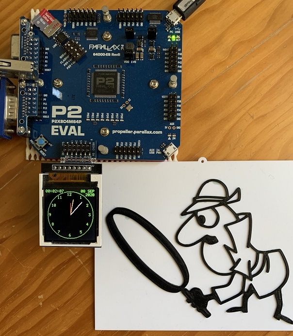
Here is a demo and driver for the cheap ILI9152 1.44" Color 128x128 LCD available on fleaBay for around $4.
There are routines to draw lines, circles, fill, and a clock face.
There are both 6x8 and 8x8 character fonts included.
Note setting the time is left as an exercise for the user
Note: The LCD plugs into 8 I/O lines which also provides power and ground to the LCD from P2 I/O pins. The LCD draws minimal current - I've also done this with P1.


Comments
You can't buy the small one by itself but they do sell a larger board individually.
There has been a bit of confusion on the net about kynar wire, but this is normally the standard wirewrap wire that you strip and solder as nobody actually wirewraps these days (I hope). Some apparently don't bother to strip this but melt through it instead?
There is the other kind of prototyping wire called verowire or magnet wire with a polyurethane coating that melts at around 350'C so there is no need to strip it, just use a hot iron. I see that prototyping with this has been taken to the extreme and used for BGA packages (check this page).
I used to use this verowire with a wiring pen and neat wiring combs so that I could run the wire through all the connections and even wrap around a component or socket lead once or twice, then proceed to the next connection etc, all without lifting the pen. Then I would solder up all the joints and then use a craft blade to cut the wire where it should have been cut as it jumped to a new connection. It really created a very neat, tidy, compact and reliable prototype on matrix board.
btw, please never use "veroboard strip", it is the ugliest most useless prototyping board for anything beyond the 70's (that's half a century ago). Always use plated-through tinned and solder-masked uncommitted matrix board that doesn't try to (in)conveniently join pads together in buses or DIP patterns.
@Cluso99 - I started looking at some I2C displays that would fit on the back of a P2D2. That are cheap and it sure would be neat!
Some of the wire-wrap wire of the late 70's (the wire-wrapping heydays) had a brittle style coating that would open when the wire was wrapped around a square post, which avoided the requirement to strip the wire first. Many mini-computer motherboards in those days were wire-wrapped.
I found it was useful to make compact boards, though a bit tedious to strip all those wires to the right length. Downside were the prices of all the sockets which typically cost a lot more than the logic ICs. I ended up doing a hybrid thing where I soldered boards with thin wire wrap wire for a few prototypes. Usually turned into a major rats nest by the end but it mostly worked out. Only <20MHz stuff, wouldn't think of it with the P2 now.
For laughs I thought I would power it up and see what happens.
It still works!
BTW Here's a picture of one of the first Apple Mac wire wrap prototypes.
It was not unusual to prototype this way back then.
That last picture (bh2pH.jpg) reminds me of a nightmare keypunch interface project I inherited. The University library used punch cards to track the books and wanted the computer to punch the cards using one of the serial ports. The interface consisted of two boards pop riveted together and wired using a "slit & wrap" tool, and the resulting mess was mounted on top of the keypunch electronics chassis. I spent days chasing down intermittent connections before biting the bullet and soldering all the wires to the pins.
It was a little embedded system that ran my own virtual machine and had custom byte-banged colour VGA graphics&text video output hardware and PS/2 keyboard, serial port, plus an SD filesystem and amplified synthesized audio. I think it was done in the mid 2000's with an AVR prototyping board before I eventually got into Propellers which would have simplified things big time and made most of it fit in a single chip apart from memory perhaps.
I did the double decker RAM thing to get up to 128kB of memory which could be bank switched into the 64kB address space and half could be used for video buffers etc. It was a fun project and entirely home grown. Can't say I'm too proud of the etched layout though, what was I even thinking back then? That layout was probably whipped up in 15mins in some dodgy windows paint software by the looks of it, at least it worked.
Oh man what a nest. Happy days, before race conditions...
At the time, logic circuits were not that cheap, and bucket-brigade delay lines were on shelves, whenever timing goes haywire.
Cheapo solutions demanded those "mystery", low-valued, ceramic caps and resistors. I used to hate them, deeply.
Someday, somewhere, PVT would left you "mostly" naked, on the street: phone calls, angry customers....
PVT is the short form for Proccess Voltage Temperature:
signoffsemi.com/pvt-rc-variation-ocv/
I've no idea about the first time I'd saw it being used here, or from whom, but I'm sure it was at P2 forum threads.