Identify schematic symbol
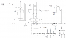
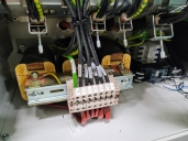
I'm trying to diagnose a voltage issue on a machine I'm working with. In the schematic, 480v current goes through the K120 contactor, into -L001, and comes out as 960v and into the G100. The manufacture claims that -L001 is NOT a transformer and is "just a line filter" and wants me to replace G100 which is a $9000 part. They claim I am getting feedback from G100 causing me to get the voltage spike, even though I measure voltage with the wires disconnected from G100. From what I can find, U/V/W1 and U/V/W2 are drawn in as inductors and with 3 of them next to each other in close proximity, it should be a transformer. Please correct me if I am wrong, as I've been working on this machine for 2 weeks fixing problem after problem. I've attached the schematic as well as the large object in question for reference.


Comments
It's a current-limiting device which also filters out spikes. If you search for those names I gave above, you will find pictures, and suppliers that will sell you an equivalent component. You have to specify the working voltage, current, and either the reactance, L, in henrys, or the AC impedance in ohms. You can convert reactance to impedance by multiplying by 2 x Pi x f, where f is the frequency of the supply.
There's not much to go wrong with a 3-phase choke, so providing it looks intact, the contacts are tight, and you can't see or smell any burning, then it's unlikely to be the cause of the fault.
You should check the resistance (with the supply disconnected, of course) of each phase with a multimeter, measuring from L1 to L1.1, and similarly for L2 to L2.1 and L3 to L3.1. Your multimeter will measure the DC resistance, which should be very low - and the readings for each phase should be about the same.
Got very low resistance on each line, and everything is snug. I just don't understand how the G100 can cause a voltage spike that big. Guess I'll have to replace it. I appreciate the clarification!
Dumped the WAG.
How were you measuring 960V? That is the P-P value of 480RMS. Looks like the input of the G100 may be a 3 phase rectifier. Could be a part failure there, though you did mention that your measurements were with the G100 disconnected.
Pardon the curiosity / kibitzing, frustrating equipment problems to you, interesting puzzle to me. Good luck, let us know what the answer was if you get time. Thx.