

PAB running a program for an Adafruit camera board
 Buck Rogers
Posts: 2,216
Buck Rogers
Posts: 2,216
in Propeller 1
Hello!
Not too long ago I bought a pair of the camera boards, and they are calling them, "Mini Spy Camera with Trigger for Photo or Video".
I then asked in this one "Translating the Arduino Sketches into a SPIN function" for some help to translate the sketch inside into a Spin program. That effort turned into this gem:
And I decided to confirm that it works, actually @Ariba I never doubted you, but the computer did. Also the PAB and the QS. Right now I have it running and collecting photos.
I also made up a breakout board to connect the board to the host. I used one of these:
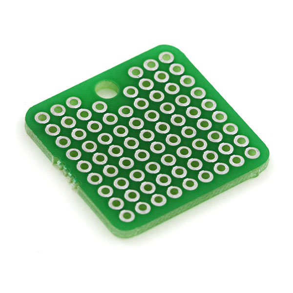
That guy is this thing, ProtoBoard - Square 1" Single Sided It is from Sparkfun, out there in Colorado. They come in pairs so the other one was wired to facilitate powering the QS which is next after I properly grok the means of sending it power via a pair of regular batteries.
So the idea makes sense at that level.
Now the problem becomes that of applying the technology to the QS boards.
--
Mascot asleep.
Not too long ago I bought a pair of the camera boards, and they are calling them, "Mini Spy Camera with Trigger for Photo or Video".
I then asked in this one "Translating the Arduino Sketches into a SPIN function" for some help to translate the sketch inside into a Spin program. That effort turned into this gem:
CON
  _clkmode  = xtal1 + pll16x
  _xinfreq  = 5_000_000

  trig = 0     'pins
  led  = 1

  OUTPUT = 1
  LOW    = 0
  HIGH   = 1

PUB setup
  dira[led]  := OUTPUT
  dira[trig] := OUTPUT

  outa[trig] := HIGH
  outa[led]  := HIGH

  repeat
    loop

PUB loop
  outa[trig] := LOW
  outa[led]  := HIGH

  delay(50)

  outa[trig] := HIGH
  outa[led]  := LOW

  delay(5000)


PRI delay(ms)
  waitcnt(clkfreq/1000 * ms + cnt)
And I decided to confirm that it works, actually @Ariba I never doubted you, but the computer did. Also the PAB and the QS. Right now I have it running and collecting photos.
I also made up a breakout board to connect the board to the host. I used one of these:
That guy is this thing, ProtoBoard - Square 1" Single Sided It is from Sparkfun, out there in Colorado. They come in pairs so the other one was wired to facilitate powering the QS which is next after I properly grok the means of sending it power via a pair of regular batteries.
So the idea makes sense at that level.
Now the problem becomes that of applying the technology to the QS boards.
--
Mascot asleep.
Comments
Hello!
Update: I spent two days, yesterday and all of today trying to grok how to make the original code run on the Arduino properly. That was done on one designed by Adafruit for the Makershed gang, and inside an Altoids tin.
First it worked, and took photos, and then it stopped.
Now it is again running on the same PAB, and this is one of #32910, the original design. I'm going to keep running it that way until the card is fully loaded with photos. Or something like that.
Next will be to move it to a Mini Prop board.
Mascot asleep again.
Well done buck!
Can you share your code and hookup details. This looks like a useful project!
Hello!
Code for it? Sure:
CON
  _clkmode  = xtal1 + pll16x
  _xinfreq  = 5_000_000

  trig = 0     'pins
  led  = 1

  OUTPUT = 1
  LOW    = 0
  HIGH   = 1

PUB setup
  dira[led]  := OUTPUT
  dira[trig] := OUTPUT

  outa[trig] := HIGH
  outa[led]  := HIGH

  repeat
    loop

PUB loop
  outa[trig] := LOW
  outa[led]  := HIGH

  delay(50)

  outa[trig] := HIGH
  outa[led]  := LOW

  delay(5000)


PRI delay(ms)
  waitcnt(clkfreq/1000 * ms + cnt)
Now as for wiring it, the thing has three leads, a Red Wire and a Black Wire and a White one. The Red and Black go to the Positive at 3.3v or 5v and ground respectively. And the white one goes to the P0 connection. Include a red or green LED plus a 1K resistor to Ground to show that the thing is running.
Now the camera you buy from Adafruit (look under spy camera or cameraboard) will not have a white wire, it will have a green one. It is believed that it will work the same way. Use a Micro SD card of small size and format it as FAT32 to work. It will keep going taking photos until it reaches the 999 count normally, or that if you're running it on battery after programming it, and the batteries are rechargeable then it will also stop running when they do.
Also no mascot was involved in the creation. Just a lot of help.