

Retro II - An Apple II Compatible 6502 Computer
 Jon_Thomasson
Posts: 44
Jon_Thomasson
Posts: 44
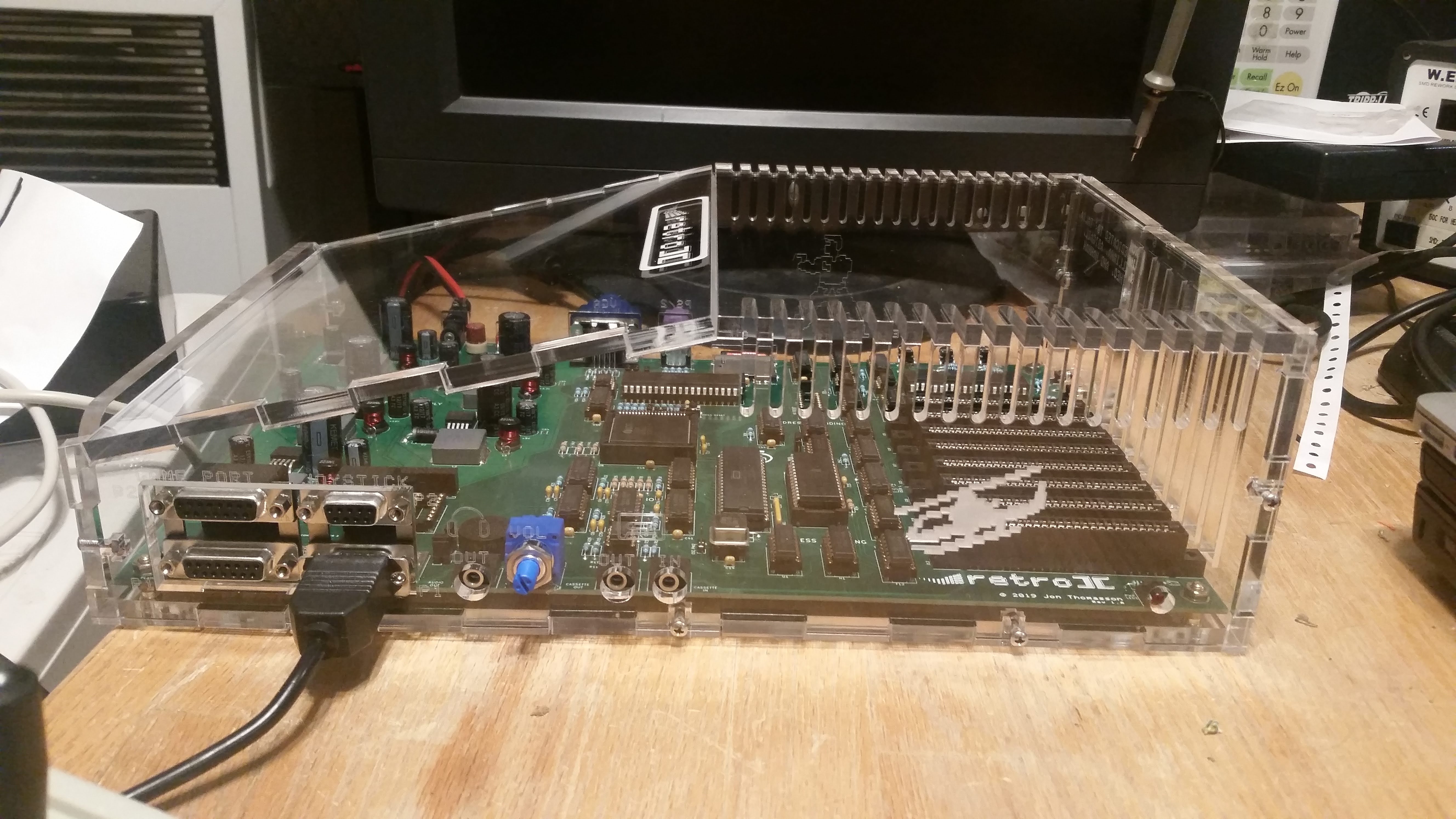
Here is a project I've been working on that has not one, but two Propeller's onboard! I call it "Retro II" (every project should have a name, right?). It's a homebrew 6502 computer that plays Apple II games. The computer also has two 15 pin game ports, two 9 pin Apple II joystick ports, cassette in/out, built in speaker/volume/headphone out, vga, ps/2, sd card, and 8 peripheral slots.
Here is a short overview video of the finished computer: https://youtu.be/tcg8ul2Vst0
I've always had a love for the Apple II. It was the computer we had in our computer labs growing up. My mom was a teacher and somehow she was able to purchase one for our family. I still have a lot of fond memories of that computer, and I really wanted to see if I could recreate it in some way now with more modern hardware.
Some basic design decisions for the project. I wanted it to feel like an 80's era computer, with the big beefy through hole components and the big green PCB. I wanted to have it be a learning tool as well. I didn't want to stick everything in an FPGA, because I wanted my kids to be able to see the individual pieces that make the computer work. It also needed to be made of all off the shelf parts that you can buy today and are still manufactured. It needed to interface with modern keyboards and monitors and storage.
I started with the original Apple II schematic and quickly realized that there were going to be a few hurdles. There were several components like the keyboard encoder, DRAM, and 558 timer that were no longer manufactured. In looking at the timing of the system, everything was really tightly coupled and complicated. The timing for the video signals, keyboard multiplexer, and RAM access were all woven together in a beautiful tapestry by Steve Wozniak. But I wanted to see if I could simplify it a bit. This is where the Propeller got involved!
I initially just used a 1MHz oscillator to drive the clock, later on I wired up one of the Propeller's to generate the clock signal. This enabled me to do some neat things like overclocking/underclocking the computer. I can also stop the clock to pause program execution if I want to debug something. I took out the 24 DRAM chips and replaced them with a single dual port static RAM. I also consolidated the six ROM chips into a single ROM. By using dual port RAM, I was able to hook up the other Propeller to read from the video portions of RAM and draw out the VGA signals without interfering at all with the rest of the computer. After decoupling the timing a bit, there were a few small changes to the address decoding in order to ensure it was reading/writing to RAM at the correct times. In addition to handling the timing for the system clock, Propeller 1 also reads the soft switches and relays that data to the video processing Propeller. It also handles reading from the SD Card, parsing the DOS images, and handling the PS/2 keyboard. The two Propeller's talk to each other via an I2C bus.
The video processing Propeller took quite a bit of time to optimize at least for the hires mode. To get things running initially I created a very simple memory monitor in Spin in order to test out reading/writing to memory. The easiest video mode was of course just the full text mode. Initially I used Mike Christle's VGA display driver with the C64 font. After getting text mode working reasonably well, I started to convert the driver incrementally so that it would work with the original Apple II 7x8 fonts. To do this I used a lookup table that mapped between the 8x8 and 7x8 graphic columns.
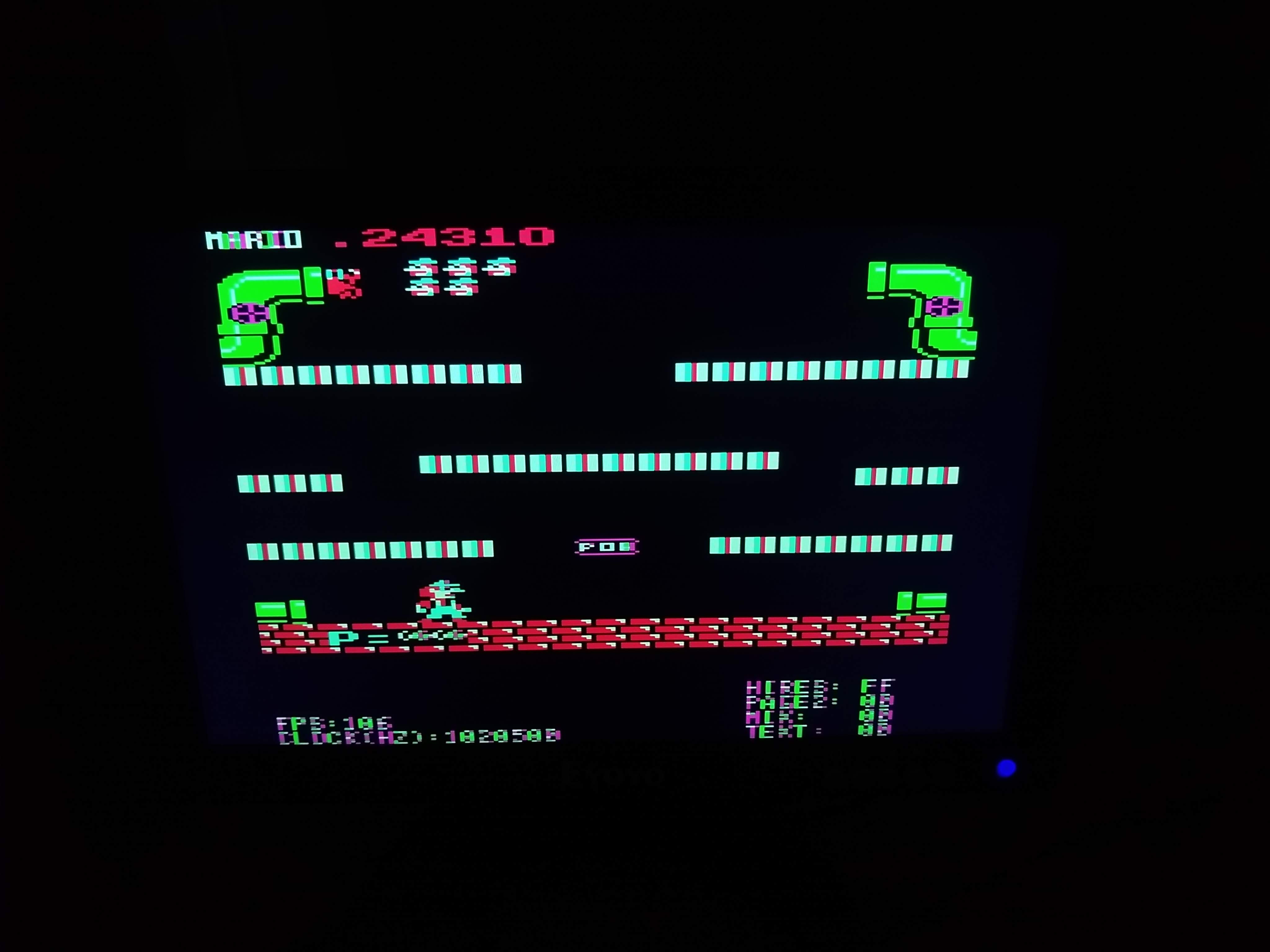
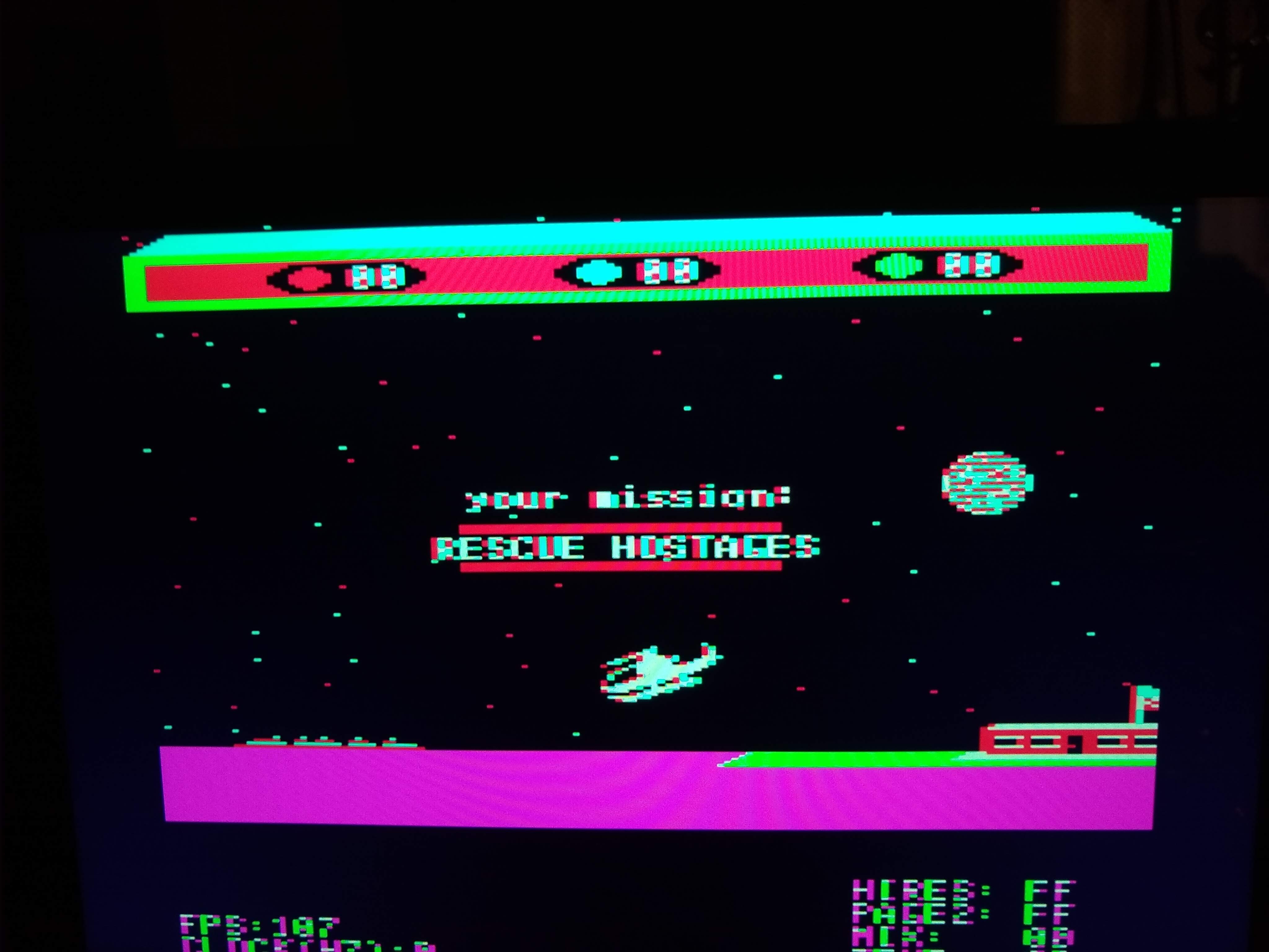
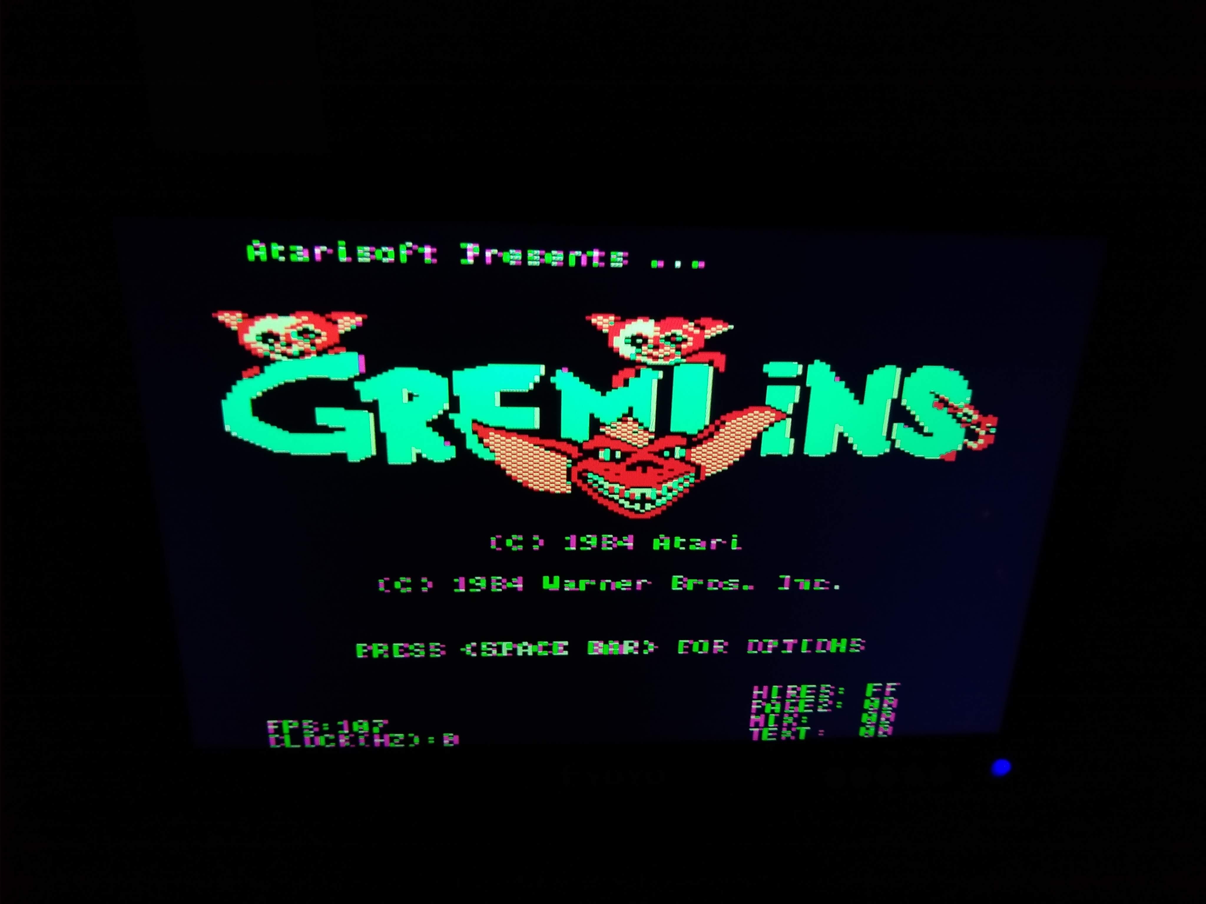
The hires video mode probably took the greatest amount of time to really optimize. I made use of the book "Apple II Computer Graphics" by Ken Williams, and Bob and Lisa Kernaghan to understand how the video memory was laid out. The hires memory map for the Apple II divided the screen into three main sections. Each section has 8 rows. Each row was divided into 8x8 boxes. So each of these boxes is made up of 8 bytes. But then the bits are displayed in reverse order and the left most bit isn't displayed at all. So that was fun to figure out. I initially had hires mode programmed in Spin to just get the picture working. Not surprisingly though, Spin was pretty slow at drawing each hires frame (about one frame every 5 seconds!). I slowly started optimizing The Spin code, to where it was drawing 1 frame a second. Then I converted the Spin into PASM, which eventually I was able to achieve 50 frames per second! I figured that I could further optimize the frame rate if I divided up each of the three screen sections and had a separate cog processing each section. But I was pretty happy overall with the finished frame rate. Right now the computer draws the picture in one of seven monochrome colors. The nostalgia for me was for the green display, so that's what I set up initially. I may try to implement the full color graphics eventually. It's a little more complicated with the way the Apple II displays color pixels, and I'm not quite sure that the Propeller would support all the colors with the desired screen resolution.
There are still a few things to nail down with the current system. In order to support some of the peripheral cards I would like to use, I need to wire up the Propeller to generate the Phase 1 clock, which is just the inverted main clock, and the Q3 signal, which seems to be a 2MHz clock. I also discovered that my game port controller buttons need some rewiring to get them to work properly. My +-12V switching supply also needs to be fiddled with some more. It works, but it has a really high current draw initially before the output caps are charged. Other than that, there's four bodge wires on the bottom of the pcb, nothing too major, but something to fix with the next board revision.
I'd really like to thank the Parallax community for giving me the tools needed to get this project working. I've listed a few of the modules I'm using below, along with their author:
I2C Slave/Master module - Chris Gadd
fsrw - Tomas Rokicki and Jonathan Dummer
PS/2 Keyboard Driver - Chip Gracey
Button.spin v 1.00 - Kyle Crane
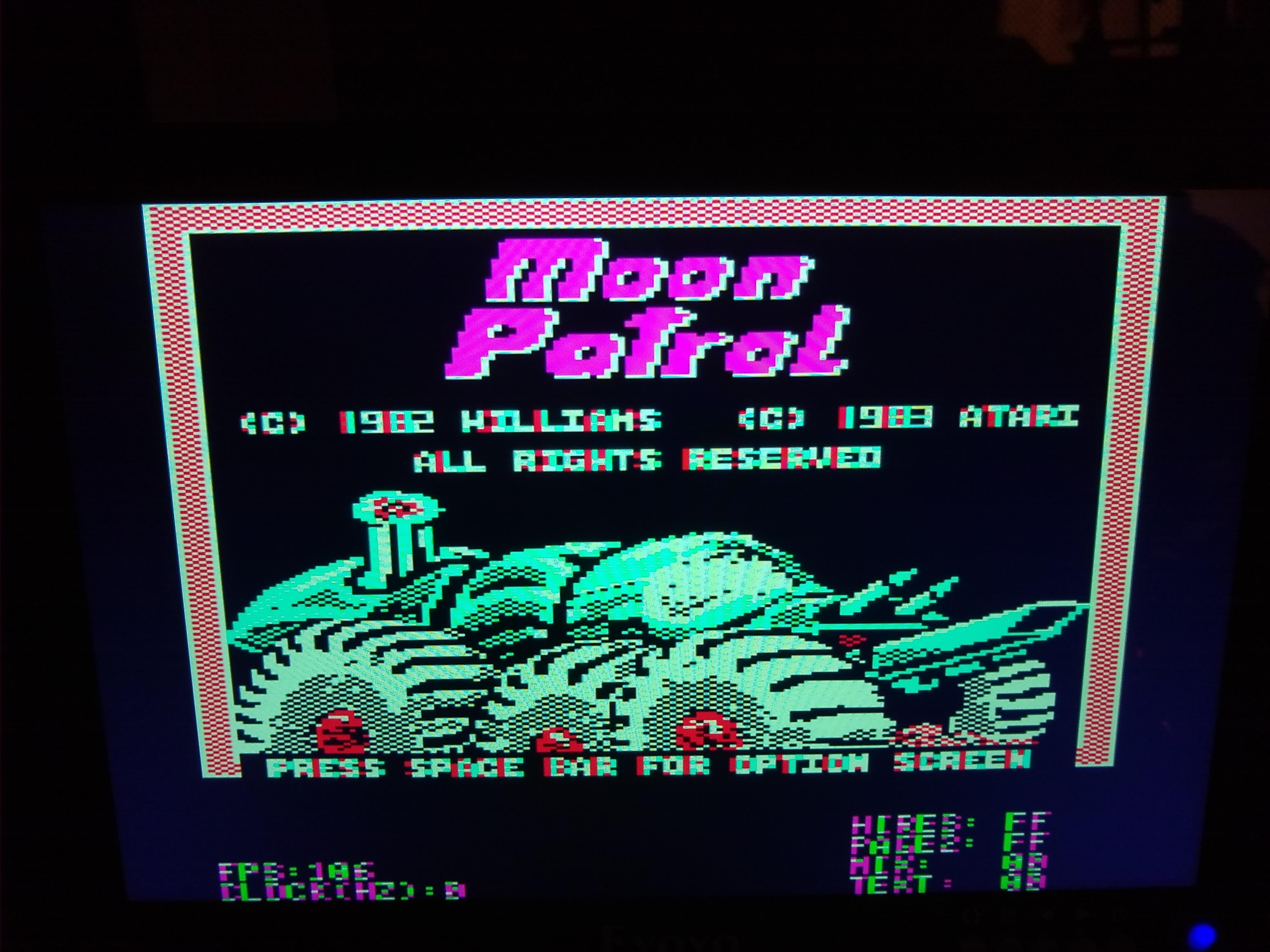
**Update 9/15/2020** I have color mode working!
Here is a short overview video of the finished computer: https://youtu.be/tcg8ul2Vst0
I've always had a love for the Apple II. It was the computer we had in our computer labs growing up. My mom was a teacher and somehow she was able to purchase one for our family. I still have a lot of fond memories of that computer, and I really wanted to see if I could recreate it in some way now with more modern hardware.
Some basic design decisions for the project. I wanted it to feel like an 80's era computer, with the big beefy through hole components and the big green PCB. I wanted to have it be a learning tool as well. I didn't want to stick everything in an FPGA, because I wanted my kids to be able to see the individual pieces that make the computer work. It also needed to be made of all off the shelf parts that you can buy today and are still manufactured. It needed to interface with modern keyboards and monitors and storage.
I started with the original Apple II schematic and quickly realized that there were going to be a few hurdles. There were several components like the keyboard encoder, DRAM, and 558 timer that were no longer manufactured. In looking at the timing of the system, everything was really tightly coupled and complicated. The timing for the video signals, keyboard multiplexer, and RAM access were all woven together in a beautiful tapestry by Steve Wozniak. But I wanted to see if I could simplify it a bit. This is where the Propeller got involved!
I initially just used a 1MHz oscillator to drive the clock, later on I wired up one of the Propeller's to generate the clock signal. This enabled me to do some neat things like overclocking/underclocking the computer. I can also stop the clock to pause program execution if I want to debug something. I took out the 24 DRAM chips and replaced them with a single dual port static RAM. I also consolidated the six ROM chips into a single ROM. By using dual port RAM, I was able to hook up the other Propeller to read from the video portions of RAM and draw out the VGA signals without interfering at all with the rest of the computer. After decoupling the timing a bit, there were a few small changes to the address decoding in order to ensure it was reading/writing to RAM at the correct times. In addition to handling the timing for the system clock, Propeller 1 also reads the soft switches and relays that data to the video processing Propeller. It also handles reading from the SD Card, parsing the DOS images, and handling the PS/2 keyboard. The two Propeller's talk to each other via an I2C bus.
The video processing Propeller took quite a bit of time to optimize at least for the hires mode. To get things running initially I created a very simple memory monitor in Spin in order to test out reading/writing to memory. The easiest video mode was of course just the full text mode. Initially I used Mike Christle's VGA display driver with the C64 font. After getting text mode working reasonably well, I started to convert the driver incrementally so that it would work with the original Apple II 7x8 fonts. To do this I used a lookup table that mapped between the 8x8 and 7x8 graphic columns.
The hires video mode probably took the greatest amount of time to really optimize. I made use of the book "Apple II Computer Graphics" by Ken Williams, and Bob and Lisa Kernaghan to understand how the video memory was laid out. The hires memory map for the Apple II divided the screen into three main sections. Each section has 8 rows. Each row was divided into 8x8 boxes. So each of these boxes is made up of 8 bytes. But then the bits are displayed in reverse order and the left most bit isn't displayed at all. So that was fun to figure out. I initially had hires mode programmed in Spin to just get the picture working. Not surprisingly though, Spin was pretty slow at drawing each hires frame (about one frame every 5 seconds!). I slowly started optimizing The Spin code, to where it was drawing 1 frame a second. Then I converted the Spin into PASM, which eventually I was able to achieve 50 frames per second! I figured that I could further optimize the frame rate if I divided up each of the three screen sections and had a separate cog processing each section. But I was pretty happy overall with the finished frame rate. Right now the computer draws the picture in one of seven monochrome colors. The nostalgia for me was for the green display, so that's what I set up initially. I may try to implement the full color graphics eventually. It's a little more complicated with the way the Apple II displays color pixels, and I'm not quite sure that the Propeller would support all the colors with the desired screen resolution.
There are still a few things to nail down with the current system. In order to support some of the peripheral cards I would like to use, I need to wire up the Propeller to generate the Phase 1 clock, which is just the inverted main clock, and the Q3 signal, which seems to be a 2MHz clock. I also discovered that my game port controller buttons need some rewiring to get them to work properly. My +-12V switching supply also needs to be fiddled with some more. It works, but it has a really high current draw initially before the output caps are charged. Other than that, there's four bodge wires on the bottom of the pcb, nothing too major, but something to fix with the next board revision.
I'd really like to thank the Parallax community for giving me the tools needed to get this project working. I've listed a few of the modules I'm using below, along with their author:
I2C Slave/Master module - Chris Gadd
fsrw - Tomas Rokicki and Jonathan Dummer
PS/2 Keyboard Driver - Chip Gracey
Button.spin v 1.00 - Kyle Crane
**Update 9/15/2020** I have color mode working!

5312 x 2988 - 539K
5312 x 2988 - 1M

3264 x 2448 - 1M
4096 x 3072 - 250K
4096 x 3072 - 457K
4096 x 3072 - 1020K
4096 x 3072 - 299K
Comments
Graphics wise, you can definitely do color and lots more. If I found the right file (your repo is a bit messy), I see that your video code isn't very efficient, so there's a lot of wiggle room for new features:
- VRAM access (read_byte) always fully sets up everything from scratch when as far as I can tell, you could just leave the address on the bus and do an "add outa,#$100" in the inner "hires_col" loop to get it to give you the next byte
- You're using a big bitmap in Hub RAM - the good(tm) way of doing graphics on the propeller is to render in real-time so you only have to buffer a few lines ahead of the video scanout (which of course requires the rendering code to be able to keep up with it). Another option is to do the rendering in-line with the video generation (a bit tricky, especially with VGA)
- lots of minor "this guy isn't very experienced with PASM"-isms. Just some from the aforementioned read_byte routine:
                        andn    outa, ram_lsb_mask
                        andn    outa, ram_msb_mask
                        andn    outa, ram_a15_mask
Unless the timing of the OUTA write is important, avoid doing multiple operations with constant S. In this case you'd do something likeandn outa, ram_all_mask '' where ram_all_mask is the values of ram_lsb_mask,ram_msb_mask and ram_a15_mask ORd togetherIt's always faster and smaller that way.shl ram_a15, #17 and ram_a15, ram_a15_mask andn outa, ram_a15_mask 'clear first or outa, ram_a15This is a job for MUXC and a constant:test ram_a15, ram_a15_mask_shr_17 wc muxc outa, ram_a15_mask '' where ram_a15_mask_shr_17 is the value of ram_a15_mask shifted right by 17mov draw_tmp, ina and draw_tmp, #255 mov ram_read, draw_tmpWhy the draw_tmp register?mov ram_read, ina and ram_read, #255These are just a some random ones that jumped out at me in that function alone. I'm not trying to be rude or anything, I'm just saying that if you put some work in, you can get a good bit more out of what you got.If you want more questionable wisdom to spew from the fountain that is my keyboard, just ask.
I won't claim to be an expert in PASM, thank you for all your advice!
This is cool. I thought I needed a pixel buffer, but if I don't then that would definitely free up some Hub RAM. Do you have any example code for this technique? Thanks in advance!
I don't really have a clean example (I think I've seen one somewhere in the depths of the forum...), but you can take a look at my VJET graphics driver to see the line buffer technique in action. It draws filled vector graphics to a composite monitor, so it's very different from what you need, but the important thing to notice is the synchronization between the render cogs (in this case there's usually 3 or 4) and the output cog.
A simple explanation of how it works:
- There's an 8 line buffer (in this case, 256 pixels wide at 8bpp), which the output cog just vertically repeats down the screen
- While doing that, it writes it's Y position to RAM
- The render cogs update the lines of the buffer that aren't currently being read
VJET renderer: https://github.com/IRQsome/Spin-Hexagon/blob/master/VJET_v00_rendering.spin
VJET output: https://github.com/IRQsome/Spin-Hexagon/blob/master/VJET_v00_composite.spin
Whilst working in a computer store in Forest Hills NY, I found that I still remembered the binary squawks that an unhappy Apple would make when there was trouble. And in this case the sound the machine made was for "Help! I've blown my ROM!", to the sounds R2 makes when he would be blasted from the Star Wars films. I so advised the surprised intern and the tech about that. The intern was annoyed, and the tech was pleased.
Good showing there @Jon_Thomasson that was amazing.
Thanks @mpark ! I was thinking of putting an Apple for scale instead, but figured the "banana for scale" meme was more well known.
That's a great analogy @"Buck Rogers" with the R2 sounds. I think I've heard some of those same sounds come out of an Apple as well. Good memories! Working at the computer store sounds like it would have been a fun job.
Apple ][ was what I learned on, too, back in 1980. Steve Wozniak really did things well. When I got into the C64, I couldn't figure out what the problem was, but it was just a general lack of quality. It took a long time for me to realize that Wozniak didn't just make the Apple ][, but that he had made it exceedingly well. He set a very high standard that I had taken for granted. The C64 hardware was neat, but its firmware was such a mess. Anyway, the Apple was magical to me.
I will watch your video now.
Chip, thank you for the kind words! I agree Wozniak really made an amazing computer. That's been part of the fun for me with this project, just getting the opportunity to see how well the original Apple II was engineered. You can really see that he put his passion for engineering into every part of the computer. With the Apple II, Woz wanted people to not only use the computer, but also understand how it worked. Then he added all of those expansion ports to it so people could make it do whatever they wanted it to do. And the whole thing came with not only a user manual, but the schematics and source code! After Woz stopped engineering for Apple it seems like a lot of the openness and simplicity went away.
Thanks again!
Yes, I bought a Mac when it came out and, for a few days, I figured I just wasn't finding the manuals for how to program it. Someone who knew had to explain to me that you must register as a developer to write software for it. I couldn't believe it. It was like a betrayal.
Steve Wozniak is still very freedom-minded and avoids getting boxed into controlled schemes.
It's probably occurred to you that you could, if you wanted, realize your entire Apple ][ project in a single P2 with an 8-pin 16MB flash chip. Might be kind of fun. If you are interested in looking into it, I will send you a P2 Eval board, which is all you'd need.
You know I was thinking it'd be nice to replace the two P1's with a single P2. But it hadn't occurred to me that I could possibly stuff everything into a P2. That would actually be pretty cool. I need to catch up with the P2 development it seems.
I do have a P2 dev board that I bought back in late 2018 but sadly I haven't done much with it yet. This may be the excuse I need to get the ball rolling. Thanks
See my Propeller 2 OS - it's alive! And CPM2.2 is running! thread
https://forums.parallax.com/discussion/comment/1499300
The P2 emulates the Z80 plus extra code to make the SD card FAT32 files look like CPM disk drives, provide serial interfaces and a few other things.
We did the same on P1 but because of the limited RAM we needed to add an external SRAM. The P2 has 512KB of hub RAM so no need for external SRAM. On the P1, the Z80 ran about the same speed as a 4MHz Z80. While I have no timing info yet for the Z80 on P2, I am initially expecting 10x performance, and there are other things to do to increase this substantially.
The 6502 is a much simpler and more regimented instruction set so it will be much easier to do. Of course the specifics of the hardware that Woz did in the Apple will need to be implemented in software but I wouldn't expect too many problems here.
The one issue on the Apple that I am aware of is the way adjacent pixels on the color screen are used to get alternative colors. I am unsure if this is possible and how it could be done.
Nice work with Propeller 2 OS! That's really impressive. I was reading up on the P2 some more last night, and getting excited about the possibilities.
You're right about the weird color issues with the Apple II. That's part of why I only implemented the monochrome screen originally. It seems like there must be a way to do it though.
To actually decode the color in software seems somewhat tricky. As far as I can tell, it can be thought of as a simple 2bpp encoding, except bit7 is used to select the palette, which incurs the problem of each byte containing 3 whole pixels and a half-pixel (What happens when a colored pixel is on a palette boundary? Seems like a rare edge-case). (In reality the palette select also shifts the pixels of that byte by a quarter-pixel, but that seems negligible for color mode).
Here's what I'd do to do the color decoding on P1 - not sure if that'd work properly, don't have experience with apple graphics:
- read data from video RAM and rearrange such that an original byte pair %A_BCDEFGH,%I_JKLMNOP is written to the internal buffer as a word %AI_JKLMNOPBCDEFGH
- write the video output code to display a 3 pixel slice and a 4 pixel slice with selected palettes, kinda like this (might be too slow for VGA rates? OTOH this is really low-res.) :
mov iter,#20 '' pretend we initialite pixel_ptr here :xloop rdword pixels,pixel_ptr add pixel_ptr,#2 test pixels,bit15 wc muxc :wv1,bit9 mov vscl,vscl_3pixels :wv1 waitvid palette0,pixels test pixels,bit14 wc muxc :wv2,bit9 shr pixels,#6 mov vscl,vscl_4pixels :wv2 waitvid palette0,pixels djnz iter,#:xloop '' must be aligned to 2 longs palette0 long 1234 ' pretend this is the white-purple-green-black palette palette1 long 5678 ' pretend this is the white-blue-orange-black paletteThat's a good way of thinking about bit 7. It's just in charge of selecting which palette to display, either black/green/violet/white or black/orange/blue/white. I may load up an emulator later on to see if I can nail down exactly what's going on. Thank you for that code also, that'll give me a great start. Really appreciate it, thank you!
Most computers have 8 bits aligned on a color cycle boundary. Even bits are always the same color no matter whether bytes are odd or even.
The high bit shifts output by a half pixel, resulting in that byte being able to enable display of white, black and either:
Red / Blue
Green / Cyan.
The apple bit patterns repeat every two bytes, not every single byte like pretty much every older computer does.
Two bytes = 14 pixels, or 7 color pixels depending on whether a color composite display and the color burst are present and enabled.
There are edge cases: one byte high bit set, next byte not and some bit patterns show additional colors at times.
For most purposes, treating it like a 2bpp display that repeats color by pixel mapping every two bytes will work.
Unlike most color displays, a single pixel can have color, where most 2bpp displays feature pixels twice as wide as they are high. This only happens on the Apple when two adjacent even or odd bits are present.
https://mygaming.co.za/news/wp-content/uploads/2012/03/Prince-of-Persia-Apple-II-screenshot.jpg
You can see that put to use in this screen shot.
Here is the color clash and edge cases.
https://upload.wikimedia.org/wikipedia/commons/thumb/6/6a/Apple_II_high-resolution_graphics_fringe_effects.png/300px-Apple_II_high-resolution_graphics_fringe_effects.png
If it were me doing Apple HGR screens, I would read words and do color lookups on the pixels. That repeats nicely, meaning only one table needed.
If the display is 280x192, say 16 colors, apple graphics map to a small 8 color lookup table.
Is there any possibility of doing a production run, even a kit? I'll be first in line to order one.
Will an original Apple disk drive work with this?
I was thinking that going from monochrome to full color would more than double my needed pixel buffer size. But really this doesn't seem to be the case. Initially I thought that the pixel buffer should have only displayable pixels, so I was taking out the color bit prior to sending it to waitvid. But Wuerfel_21's code opened my eyes a bit. If I understand his code correctly, I can keep that color bit in the buffer, and then use it in my vga driver to switch out the color palette. Then I can control how many pixels are transmitted at a time with vscl which is pretty cool.
Of course growing up with the green monochrome screen, I was oblivious to all of this. It's both really cool, and super confusing. You can't have just a white pixel by itself. The minimum horizontal spacing to create white is 2 pixels wide which is bizarre. And then the fact that each byte has 3.5 color pixels, so you need 2 bytes in order to get 7 complete pixels. On top of that the edge cases and clashing that @potatohead mentioned. It makes things a bit complicated.
I really like @potatohead's idea of thinking about it like odd/even bytes. And then supplying a lookup table to translate the pixels into their appropriate colors. I may try something like that.
@cgracey is that streamer available in the P1, or is it a P2 thing only? That looks like a pretty cool feature.
@Whit Thanks! It's always nice to meet another Apple ][ fan.
That would be really cool. There's a few hurdles I'd have to get over though. Legally, there may be a problem if I start distributing the Apple II rom. I'm not a lawyer, so I can't really comment on it. They may not care since it's just a small project, but it still may be an issue.
The second hurdle would be the price. In order to really knock down the price, I'd need to order a lot of parts in higher quantities. I don't know if there's that much of a demand for this type of thing to warrant that.
I do have the project open source. So people can make one for themselves if they wanted to. I was also thinking that I could sell the pcb's and then provide links to the bill of materials.
In theory an original disk drive should work, although I don't have one to test it with. I have a Booti drive that uses an sd card that I want to get working with it. The issue there is that I need to hook up the Propeller to output the phase 1 clock and the Q3 signal still. I'm thinking it shouldn't be too difficult to do that hopefully.
I still have a few changes to make in the pcb where I had to bodge some wires. I'm honored to see that people think it's a cool project. Thanks!
Computer emulators generally come with the all relevant ROM images, so my theory is that no one actually cares. Another option would be to use write-protected RAM in place of ROM and somehow load that from the SD card on power-up.
https://macgui.com/downloads/?file_id=14064
The P2 has a streamer, but the P1 does not. You could do the whole thing on the P2, no other chip needed. In fact, you could probably emulate EIGHT Apple ]['s concurrently.
I think you'd need this for each Apple ][:
48KB RAM
1 cog, generates video on interrupts via streamer, main code handles emulation
1 pin for composite video out
2 pins for USB or PS2 keyboard
3 pins for joystick?
That could leave 128K of hub RAM for the Apple ][ ROM and emulator code, plus the top 8 pins free for development. The SPI flash could be shared among all Apple ]['s as a virtual drive, shared via a LOCK. You would just write ONE program to make it all happen.