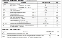
How many of this device will Prop drive?
in Propeller 1
I use this low level mosfet on many projects over the years and it works great. I have some cases where there needs to be 2 of these devices off of 1 pin. In one case it's off or on. In another case it's OFF, ON, or PWM 50% at around 15k - 17k. What would be the limiting factor if I want to run 2 devices without an issue long term? Thanks for any suggestions. If you think it's not a good idea to run both devices, I'm sending in some PCB orders today and can stick in a little buffer board. Suggestions on a buffer between Prop and 2 mosfets? I think the gate drive resistor currently used is 100ohm.
https://www.onsemi.com/pub/Collateral/FQB30N06L-D.pdf
https://www.onsemi.com/pub/Collateral/FQB30N06L-D.pdf


Comments
-Phil
Consider a low-side mosfet driver to be sure,
https://www.microchip.com/design-centers/power-management/motor-drivers/mosfet-drivers
One that myself and others here have recommended is the MIC4426/4427/4428. A dual lowside driver with input threshold of ~1.5V and an output drive capability of 1.5A at 4.5--18V.
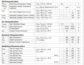
Can you point to the area of the datasheet where this information is found?
I see this and I think it should work with the Propeller at 3.3V logic.
Am I looking at the wrong parameter?
Figure 2, shows drain current vs gate-source voltage, assuming 25V on the drain and tested with a 250µs pulse. Note that you are not very high up the curve when you apply 3.3Vgs. Whether it works or not in your application depends on how much current is needed. It limits at l0 amps, so the application can't expect more than a fraction of that. It will get hotter than it would if it were driven with a higher Vgs.
Figure 3 shows drain to source ON resistance. It shows it at two values of Vgs, 5V and 10V. There is not a curve for 3.3V, however, mentally visualize a curve that lies slightly above but far to the left, with the vertical asymptote at around 10 amps. Again, a high ON resistance means a hotter transistor.
Switching speed is another thing. As Phil pointed out, the gate-source capacitance is around 1nF and has to be charged/discharged with every transition. If the gate-source voltage rises/falls slowly, the output also transitions slowly. The transistor gets hot as it goes through the linear region. You want a strong drive to make the transition fast.
That's an old fet, spec'd at 5V gate, and with a highish 2v5 gate threshold, so it will be only good for moderate currents at 3v3 gate drive. 3v3 is only 800mV above the MAX gate threshold. (250uA)
You can measure the RDSon to get an idea where you are on the curve, and warm the part to gauge temp movements.
More modern FETS come in smaller packages, with gate drives spec'd at 4.5V, or lower.
They are probably also cheaper.
15~17k is modest speed, but if you want lowest RDSon for least losses, you would use a gate-driver chip to deliver 10V to the gate.
Thank you for your detailed answer. It was very helpful.
I am curious though about the losses due to 3v3 gate voltage. In this screenshot already posted above, it suggests 3v3 to provide 2amps? The graph has 9 divisions between 10^0 and 10^1 so I am just guessing. However, with an 8amp supply, 100' 12 gauge stranded cable am I getting losses as a result of the mosfet in addition to the cable length. I adjust the voltage to 32V to compensate for voltage losses.
I don't have a 10V supply to provide the MIC4426/4427/4428 with a Vsupply of 10V, but 5V is available. Ideally I need maximum performance as this clutch is slipping under some peak loads(exceeding the working load). (Maybe a test going direct from power supply to clutch is in order to see if it cures the random slips on some peaks).
If there are losses going on here, I can make a board for the MIC4426/4427/4428, maybe drop in a 24input to 10V Switching regulator. Then drive this parts gate from the MIC4427 non inverting buffer. There is the case of the original intent of this post about possibly getting losses by driving 2 of these mosfets with a single prop pin with gate resistors at 100ohm. And the point is there can't be further losses.
eg say the fet is 100mOhms at 3v3 gate, that will drop 120mV at 1.2A
5V will certainly help, as then you hit the spec MAX rds of 40mOhms typ 35mOhms. That's then 42mV of typical drop.
That's better, but the 78mV change is modest and unlikely to be noticed by the clutch
A simple SOT23 logic buffer would be fine for 5V drive.
It is not easy finding very-low-gate drive fets above about 30V Vds *
From OnSemi, 2V is the lowest Vgs(max) for 50-60-80V fets, that's 0.5V better than what you have now.
For new designs parts like NTTFS6H860NL or NTTFS6H880NLT or larger NTMFS6H852NL, or Dual NVMFD6H846NL, are small and low cost, suited to SMT production lines.
The RDSon will be exactly the same for 1, 2 or 10 MOSFETS as they are voltage driven and present no static load to the Prop.
*Addit : I did find one new part - this is 40V, and it specs RDS all the way down to 1.5V gate drive.
VGS = 2.5 V; ID = 7.3 A; Tj = 25°C 17mΩ typ < 22 mΩ
https://assets.nexperia.com/documents/data-sheet/PMPB14XN.pdf
These Vgs threshold figures that they publish in datasheets aren't ever really useful for switching applications and you always have to have a look at the graphs which means downloading the datasheets for each one. I wish they would publish Vgs for fully on and other applicable switching parameters as well, it would make searching for suitable devices much much easier.
Anyway, most MOSFETs can handle higher gate voltages but may breakdown around 20V, so 12V drive is fine too and since the average current for drive is fairly low I would just use a small linear regulator for that with some suitable low esr bypass and bulk capacitance to match gate capacitance, so 1nf and 10uF tantalums perhaps.
Fake picture for today. I just had a quick google to see if there was any information about the caps they use on the driver supply but didn't see anything at a casual glance. However there is this photo of a well dressed "test engineer" at his "test bench" set beside the bright sunny window. Man, I had a great laugh for a whole variety of reasons. Anyway, besides pulling in every bit of old and new test equipment that works or doesn't work, and piling them on top of one another, they missed the absolute obvious fact that this would be very impractical and useless. For one reason, they are useless unless you connect up the probes and leads, and if you did that, you would probably need cable guides of some sort and then the remaining working area would disappear under the mass of cables!
'fully on' is an elastic concept with a MOSFET
I'm not sure how this OnSemi search link will copy,
In that search, I asked for N-fets from 40~100V, and it tabulates the 4.5V RDS and 2.5V RDS (reveals none)
You can also sort by Vgs(on) column and that reveals that 2V is the lowest Vgs for high power parts, with 40V and up VDS.
I see it as 20 amps, not 2 amps, shown by red lines in figure 2 redrawn below, with ~3.3Vgs. Remember that the graph is drawn with 25V applied directly from drain to source. The fet is basically a short circuit across the power supply, a power supply capable of providing at least 20A at 25V. The fet intrinsically limits the current to 20A at a Vgs of 3.3V. The measurement is made quickly, with a pulse of 250µs. Otherwise the fet would heat up and burn out quickly. Note that the tested limit is up to nearly 100A under the conditions of higher Vgs. Another graph in the data sheet (safe operating area) shows how much current can be supported for how long. That includes a safe operating area for continuous operation. There is also a graph for thermal considerations.
I also sketched a load line for a 10Ω resistor on figure 1, given a 20V power supply. That is approximately the load provided by the clutch. The load line (a curve on the log-log plot) intersects the fet curve for a Vgs=3.5V at around 100mV. So your existing 3.3V drive direct from the Propeller pin could indeed bring the voltage across the fet down to less than 100mV. You did observe that it mostly works, and that the fet is not horribly hot, or letting out smoke when switching the 1.2A load. Nevertheless, operation will be far more secure, especially for PWM, when the gate voltage is higher.
It is also important to know that fet characteristics like Vgs have very wide statistical tolerance. So one fet might work great but the next one is horrible. Better to play to the worst case.
+1 For TC4427
I've also the '4427 or '4428 to drive piezo transducers, as for generating mist. They typically take +/- 20 volt bipolar drive.
Doubling the load is a simple way to verify margins.