DC Motor RF Interference
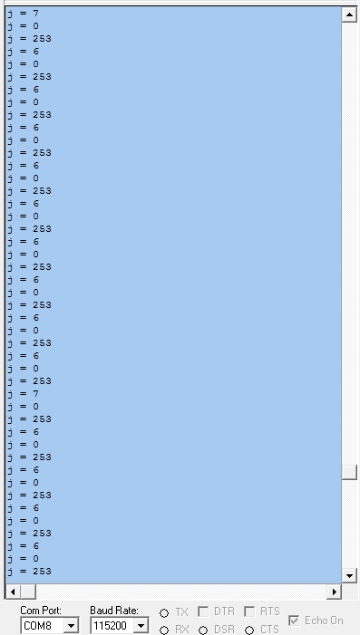
I wrote a P1 driver for 433Mhz modules that is pretty stable when I run it with no load on the serial terminal. In the screenshot "253" is the number I assigned to the drive wheels. (I want to add a panning camera and I'll assign "252" to it.)
The two values below '253' control forward or reverse speed .

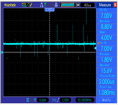
When I connect a geared DC motor the motor glitches badly. I connected a DC motor to 4V, no PWM, no diode, and connected an oscilloscope probe to the motor terminals. The 'Measure' menu shows a maximum voltage spike of 15.6V.

I'm guessing the the voltage spikes are caused by the brushes bouncing on the commutator producing RF interference. Part of the problem could be that I'm using two 'QuickStart' boards and there is not enough USB current to prevent a reset.
A diode would control the reverse spikes but it looks like I would still need capacitors to filter out the positive spikes.
I ordered some 0.1uf capacitors and I'll run some low voltage tests before I connect a Propeller. I would appreciate it if someone could offer some some advice.
The two values below '253' control forward or reverse speed .
When I connect a geared DC motor the motor glitches badly. I connected a DC motor to 4V, no PWM, no diode, and connected an oscilloscope probe to the motor terminals. The 'Measure' menu shows a maximum voltage spike of 15.6V.
I'm guessing the the voltage spikes are caused by the brushes bouncing on the commutator producing RF interference. Part of the problem could be that I'm using two 'QuickStart' boards and there is not enough USB current to prevent a reset.
A diode would control the reverse spikes but it looks like I would still need capacitors to filter out the positive spikes.
I ordered some 0.1uf capacitors and I'll run some low voltage tests before I connect a Propeller. I would appreciate it if someone could offer some some advice.


Comments
Thank you. That's what I needed to hear. I just got a scope about a month ago. I had no idea what a DC motor signal looks like on an oscilloscope. I did not know what caused the problems I had with RF motor circuits in the past.
I will breadboard the circuit before I solder caps to the motor case.
Decoupling the RF module from its supply with maybe a 10 ohm resistor and large capacitor with a small ceramic across it might help- even a small inductor in the supply near to the RF module might be worth a try.
Dave
You might find this informative- the last post has his solution
https://forums.parallax.com/discussion/100185/help-with-noise-from-motor/p1
Dave
Excellent. Thank you. That thread has tips from Beau Schwabe and Phil Pilgrim, two top engineers.