Problem with Smart-Pin Mode %10010
 JonTitus
Posts: 193
in Propeller 2
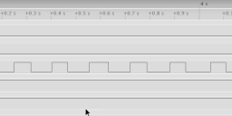
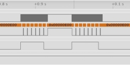
Either the Smart-Pin mode %10010 misbehaves, or I don't understand how it works, when I set for event type Y = %00 (A-input high). Modes %10 and %11 work properly. I have included my code that transmits the Z-register count via 32-bit SPI so I can capture and view it with a logic analyzer. The three LA traces in each figure below represent (top to bottom) SPI clock, SPI data, and A-input state. All versions should detect 7 events.
Image 1. Proper transmission of count data for mode %01. You can see the SPI transmission at 3.1 sec. and another transmission at about 4.3 seconds
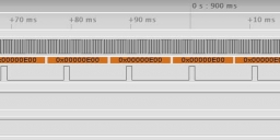
Image 2. Mode %00 operation. Two logic-1 pulses and multiple SPI transmissions during each logic-1 level. Six transmissions in the left group and seven in the right group. The third image shows expanded LA view of one SPI transmission after another.
' Mode 10010
' Synchronous serial transmission (SPI) of system-clock periods, Rev. 4, 06-20-2020 at 1100H MDT
' Positive trigger on the SPI clockpositive edge-trigger (Jon Titus)

CON
        clkout   = 40	  ' Pin P40       'Transmitter's clock out, to P31
	txout    = 41     ' Pin P41       'Transmitter data out, to P30
        A_in     = 53     ' Pin P53

dat
	org 0
	dirl    #txout				'Transmitter setup
        wrpin	sync_tx_mode,     #txout        'Set sync tx mode for pin 41
	wxpin	#%1_11111,        #txout	'Set up stop/start mode, X[5] = 1, 32 bits (31 + 1)
	dirh	#txout			        'Enable transmitter output

	dirl    #clkout				'Clock output setup
        wrpin	clock_mode,       #clkout       'Set pin as transition-output mode
	wxpin	##$1000,          #clkout       'Set base period for transition output
	dirh	#clkout                         'Enable clock-output

        dirl   #A_in	                        'Use A_in, pin 53
	wrpin  A_in_mode,       #A_in           'Set up mode for pin P53
        wxpin  #$07,		#A_in		'Wait for $7 events
        wypin  #%11,            #A_in           'Count A-input high states
        dirh   #A_in                            'Enable Smart Pin

.test_loop	nop
		testp #A_in  wc
   if_nc        jmp #.test_loop               'If C=0 wait for logic-1
                rdpin pin_data, #A_in          'C = 1, so save count
                wypin pin_data, #txout         'send count out via SPI
	        wypin #64,  #clkout           'Start clock, transmit data
                jmp #.test_loop


'=====================================

A_in_mode       long  %0000_0000_000_0001000000000_00_10010_0

pin_data	long	0

sync_tx_mode    long  %0000_1111_000_0000000000000_01_11100_0	'Positive-edge clock mode

clock_mode	long  %0000_0000_000_000000_0_000000_01_00101_0	'Clock-mode


Comments
In my software (25 MHz system clock), the value $50_0000 raises the IN flag every 0.208 msec. (The software transmits the 32-bit Z value via SPI.)
BUT: Although the first period, from the rising edge of the A-in to the SPI's first clock, also measures 0.208 msec on my logic analyzer, the Z register produces: $0927_720F rather than 0050_0000.
Try again: first period, Z = 08F9_DC5E
Once more: first period Z = 0877_94EC
For each test I recompile and run the code. Start the logic analyzer.
LA waits for a logic-1 edge on the A-input.
Press debounced switch to produce signal edge and continuous logic-1 input.
Stop LA after several seconds.
Conclusion: Something odd happens to the first Y-register value, even though the P2 has a fresh start. Why does this happen? How can I clear the Z register so the first Y-register value is the same as the others? --Jon
PS: If you keep the button pressed it'll give you a clean $50_0000.
EDIT: Clarified a little more. Certainly needs it.
Can't say I know a use for it. It's just one sub-mode of three in a pretty simple counter overall, Chip would've included it for completeness.