Robot Arm PID
 Phil Pilgrim (PhiPi)
Posts: 23,514
in Robotics
As I was developing the Blockly C code for the robot arm I built, I became aware that motion control for an arm is far different from motion control for, say, a wheeled robot. With a wheeled robot, the range of total motion can be nearly endless, depending upon the distance of travel. A robot arm is constrained by physical end-limits. For an arm, both static and dynamic loads can vary by a lot, not only from the objects they lift, but also simply by the angles of the arm sections and the varying torque due to gravity vectors. In a rolling robot, the static load doesn't vary by much on level ground, although the dynamic load can vary if it's carrying something.
My strategy for a wheeled robot was this: find the wheel that has the longest way to go. It will become the master; the other wheel, the slave. For the master, compute where it has to be and how fast it should be going, based upon ramping. Apply corrections based upon the error between that and its actual state. For the slave, compute where it has to be, based upon a fraction of the master's actual travel distance, and apply speed corrections computed from that and its own actual travel distance. That's how you get coordination between the two wheels.
The robot arm consists of three Parallax 360 feedback servos with different gearings, depending upon which arm section each controls. I fiddled with variations on the rolling robot control scheme for weeks with the robot arm and got nowhere. The nested position and velocity PID loops, replete with ramping considerations were too complicated to handle even one arm section, let alone trying to coordinate three at once.
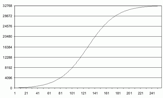
But I finally realized that the arm sections' limited ranges of motion offer significant advantages. It turns out that velocity doesn't have to enter into the 20 ms. cycle-by-cycle part of the PID loop at all; only position. And the three axes do not need to coordinate with each other on a cycle-by-cycle basis either. They operate independently but still produce coordinated motion. The secret is a modified sigmoid function:

It's modified, since a true sigmoid is asymptotic to its upper and lower limits. I changed it to reach those limits within a finite range.
The sigmoid is used with each axis of motion to project positions at each 20 ms step as a fraction of the total distance. As you can see, velocity ramping up and down is built into the sigmoid function. So it's not necessary to consider it during the step-by-step control of the motors.
The axis with the longest way to go (the master) has its step size through the sigmoid pre-computed using the arms' maximum velocity chosen by the user. Step sizes for the other arms are prorated from the master step size and the ratios of their travel distances to that of the master. From there, each arm operates independently. Motion coordination is based upon the assumption that each arm section will behave correctly on its own, using a robust position-only PID loop.
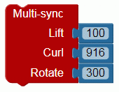
I've designed a block that performs the coordinated motion among two or more arm sections:

Its arguments are the end positions of the arm sections after the motions are complete. One application is to keep the forearm and wrist at a constant angle as the upper arm raises and lowers. Here's a short video showing how this works:
You can see a little bobble at the beginnings and ends of each movement. This is something I still need to work on. I think it relates to the coarseness of the servo feedback relative to the sigmoid at very low speeds.
-Phil
My strategy for a wheeled robot was this: find the wheel that has the longest way to go. It will become the master; the other wheel, the slave. For the master, compute where it has to be and how fast it should be going, based upon ramping. Apply corrections based upon the error between that and its actual state. For the slave, compute where it has to be, based upon a fraction of the master's actual travel distance, and apply speed corrections computed from that and its own actual travel distance. That's how you get coordination between the two wheels.
The robot arm consists of three Parallax 360 feedback servos with different gearings, depending upon which arm section each controls. I fiddled with variations on the rolling robot control scheme for weeks with the robot arm and got nowhere. The nested position and velocity PID loops, replete with ramping considerations were too complicated to handle even one arm section, let alone trying to coordinate three at once.
But I finally realized that the arm sections' limited ranges of motion offer significant advantages. It turns out that velocity doesn't have to enter into the 20 ms. cycle-by-cycle part of the PID loop at all; only position. And the three axes do not need to coordinate with each other on a cycle-by-cycle basis either. They operate independently but still produce coordinated motion. The secret is a modified sigmoid function:

It's modified, since a true sigmoid is asymptotic to its upper and lower limits. I changed it to reach those limits within a finite range.
The sigmoid is used with each axis of motion to project positions at each 20 ms step as a fraction of the total distance. As you can see, velocity ramping up and down is built into the sigmoid function. So it's not necessary to consider it during the step-by-step control of the motors.
The axis with the longest way to go (the master) has its step size through the sigmoid pre-computed using the arms' maximum velocity chosen by the user. Step sizes for the other arms are prorated from the master step size and the ratios of their travel distances to that of the master. From there, each arm operates independently. Motion coordination is based upon the assumption that each arm section will behave correctly on its own, using a robust position-only PID loop.
I've designed a block that performs the coordinated motion among two or more arm sections:

Its arguments are the end positions of the arm sections after the motions are complete. One application is to keep the forearm and wrist at a constant angle as the upper arm raises and lowers. Here's a short video showing how this works:
You can see a little bobble at the beginnings and ends of each movement. This is something I still need to work on. I think it relates to the coarseness of the servo feedback relative to the sigmoid at very low speeds.
-Phil


Comments
I like the new Block design.
I'm a complete hack!
Very impressive Phipi!
(Hangs head in shame)
I never delved into accelerations, just steady motion. To go from position to position, I just let the joint that had to move the farthest be the master. All joints incremented to their new position simultaneously, lesser-motion joints just stopped before the master.
Now I stop and bow before my master, Phipi.