

High precision encoder readout [solved] (was: Time capture on pin change?)
 ManAtWork
Posts: 2,369
ManAtWork
Posts: 2,369
I've been looking for a smart pin mode that helps to find out when the last state change of an input pin happened but I haven't found one. Maybe the "for periods ... count time" modes could be used but I don't understand how they work or what their originally intended purpose was.
Of course I could dedicate a cog and do a WAITPAT on the pin-change and record the time of the sysclock counter. But that would be a bit expensive. Say, I could poll the input pin state every 100µs and the input pin does not change more often than once per 100µs. But I'd like to know the exact time when the change happened with a finer resolution than 100µs, ideally as fine as the sysclock.
So I could
1) measure the (relative) time from the start of the last poll period to the input edge
2) measure the (incomplete) duration of the current state since the last edge (with incomplete I mean not the full time of the state until the next edge but the time until the poll)
3) capture the absolute time (CNT) at the moment of the edge.
But I don't find any of thees possibilities in the P2 smart pin docs. I only find relative measurements between pin A and pin B edges.
Any ideas?
Comments
As per the description, the prior state is captured in the C-flag buffer, so with the WC effect your code can check to confirm it is reacting to the correct edge.
If I understand that correctly then there is no absolute time and no chance to calculate an absolute time by summing up the relative durations without the risk of loosing events.
I can't read the time between the last edge and the current time (of the poll) but only the time between the last edge and the second last edge. If a short glitch happened the pulse width of the glitch would be "stolen" from my absolute time accumulator. My software polling would be forced to be fast enough to catch every single edge which is exactly what I want to avoid by using the smart pin timer.
I forgot to mention the requirement to be glitch-proof in my first post. Of course, if a glitch happens I loose precision. It's unsure if I should take the first state change before the glitch or the second after. But that doesn't matter much if only irreversible errors (summing up) are avoided.
Speed of the shaft is limited so the (average) frequency of position changes does not exceed a certain limit. But if the optical sensor is exactly at an edge of the codewheel lines the signal can "dither" between two adjacent positions at any frequency.
So any method handling the two sub-tasks in two asynchronous processes is probably doomed to fail. I also thought of counting the position with the quadrature smart pin mode and giving the position changes a timestamp with a state-change interrupt on the A xor B state. But that fails if the edge arrives exactly at the polling period boundary. RDPIN and STALLI can't happen at the same time so I don't know if the last time stamp belonges to an already counted state change or not.
So I fear I have no choice other than dedicating a cog to counting both position and time.
If I only wait for changes on (A xor B ) I could do a repeated WAITSE1 on the same condition without having to use SETPAT or SETSE1 in each iteration of the loop. So hopefully I don't loose any events. I'll try that...
If a glitch occurs the rdpin result could be +/- one count off or the time could be a few clocks off. But it doesn't cause a fatal error like lost steps or deadlocks. If a glitch or state duration is shorter than the loop execution time then an event may be lost. But the hardware quadrature counter still keeps up with the actual position. In this case the pos counter may skip specific counts but I won't notice anyway because I poll the results (pos+time) in much longer intervals of ~100µs.
Now, velocity can be measured much more precisely than +/-1 count per polling interval by calculating Of course, precautions have to be taken to avoid divide by zero or (time - lastTime) to overflow if the encoder doesn't move.
For my CNC controller project I'd like to support thread cutting with a lathe or rigid tapping with a milling machine. With the technique shown above it's possible to use an encoder with relatively low resolution (100 to 250CPR) or even a gear wheel and a inductive/magnetic sensor.
https://youtube.com/shorts/rMnpoahnbG0
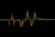
The red trace shows the speed = counts per time interval (10ms) measured the conventional way (smart pin in quadrature counter mode). The green trace shows the calculated speed taking into account the actual time the pulses (or counter changes) were recorded. The signal is noisy because I turn the encoder shaft manually and there is very little inertia. So the slip-stick effect leads to a dithery signal. There is also some cogging because the 4 discrete steps of each quadrature cycle are not perfectly equally spaced. But especially at low speeds you see the difference. The red trace jumps only between -1, 0 and +1 whereas the green trace shows gradual changes.
If you look carefully you see that the green trace reacts only to the second pulse after a direction change where the red one reacts immediately. This may look like a disadvantage, but it's not. The first pulse after a direction change only indicates that the same edge of the code wheel is passed again. That doesn't really correspond to an actual movement. It's just like a voltage meter changing it's display between +0 and -0.
What I've done in the past is a simple box filter feeding a virtual counter with 8x the resolution. It really did a good job of softening the "clicks".
It was simple because the filter time was also eight samples long. No explicit calculations for scaling. Each increment of the physical encoder became one increment for eight samples. So, eight virtual counts in total.
A sample period being one servo processing cycle.
Filtering is a good way to make something smoother. But it also adds delay. Averaging over 8 samples with 1kS/s adds an average delay of 4ms.
In my application I have one master axis (main spindle) and several slave axes which need to be moved synchronously. So at each sample point I need to know the position of the master axis as exact as possible. To calculate that I extrapolate from the last known position (current quadrature counter) by adding the current velocity times the time passed since the last recorded counter change. That is the best possible "guess" taking into account all the information that is available. It has no delay and at constant speed (theoretically) no error. At non-constant speed the error is only caused by the acceleration within the last fraction of a sample period (1ms) which is much less than the error over the last 8 samples.
4ms may not seem much. But, say, at 1000RPM the error is equal to 24°. So if you machine the same pattern once with the spindle turning clockwise and once with turning counter-clockwise both trajectories are 48° off!
Interesting. Was the objective to improve low-speed response?
It was a true follower. The machine followed the input conveyor - which wasn't a servo itself. The conveyor could operate at a wide range of speeds and was quite slow RPM at the drive sprocket where the encoder mounted. Low line rate was audible in the servos. Accessing the other end of the gearbox was painful. Initially we lived with the noise, it wasn't an operational issue but, to save some dollars on not using a 10,000 line encoder, I offered the above solution.
The spindle is also a servo in the same controller, right? The master doesn't have to follow a feedback. The master should be from the axis profile instead. Following the ideal profile not only eliminates the above lag effect, it also eliminates feedback noise injection as well. Which is the problem we had with the low line rate of the conveyor.
PS: Besides, I could visibly see trailing filter effect in your demo. The green trace lagged the red.
There is a method (that I have never tried because I've never had the low-res problem) where a history of "previous_errors" are recorded for the D term which provides the option to use a previous_error from 2/3/4 prior samples.
I wonder if this might have been an application where this could have helped.
Yeah, did that too, basically just add the measured velocity, which had its own filter, to the following target. It compensates for the positional lag at constant speed but it don't remove the noise, In fact it amplifies the noise.
EDIT: Actually, looking at the old code, I may have gone a little overboard. I've got both a Feedforward component on the PID function and also what I've called Leading on the master following function. Both have user settable gains. I suspect the PID's feedforward could have done the job but I'd only put that in because it was in the example code I started from.
The significant difference between them is likely just that Leading was applied to all following axes equally, whereas feedforward was individual to each following axis.
Here's the PID function I used:
   ax->dem = (int32)(ax->KProp * (double)ax->folerr        // Apply Proportional gain
                   + ax->KInt  * (double)ax->foltot        // Apply Integral gain
                   - ax->KDiFB * ax->vela                  // Apply Feedback gain
                   + ax->KDiFF * ax->velpf);               // Apply Feedforward gain
The differential wasn't of position error delta, but instead split between profile velocity, as feedforward, and the feedback velocity.
There was also an optional feedforward on profile acceleration but I didn't put that in.
The servos could have been a lot tighter controlled but the application didn't require precision, just had to maintain 100% accurate gear lock over the run distance.
Only ever had a use for AFF when stuck with a velocity mode drive.
On a recent re-control, the original spec for the linear axis was a FE of 73mm (!!!) @ 1000mm/sec.
I switched the drive over to torque mode for my retrofit control and with a simple P D, without much tuning effort, I achieved a FE <2mm.
Why a velocity mode drive introduces so much lag, I do not know but I rarely use that mode.
On the more expensive lathes the main spindle is also a servo drive. But cheaper retro-fits and DIY conversions from manual lathes usually have only a VFD controlled induction motor. And nearly all milling machines have VFD driven spindle motors. Especially if you want to do rigid tapping then lag is a problem because you have to reverse the rotation to get the tapping bit out of the workpiece.
Where? As I said, when reversing direction or starting from zero velocity the first pulse can't be used to calculate any velocity. You need at least two transitions to measure time between them. So when you see only one pulse the velocity could be anywhere between zero and 2 counts per sample period. A naive aproach would be to assume an average of one count per period in this case. But a rule for DSP says "always round down towards zero" to avoid unwanted oscillations.
I don't say my solution is perfect. It has limitations, of course. If you absolutely need high precision at low speed you have to use a high resolution encoder. If you have a servo then in most cases it's already there. But there are cases where a big encoder doesn't fit or the user doesn't want to pay for it. In this cases measuring time instead of just counting pulses offers a considerable advantage at very low cost.
Looks like an R-C discharge curve.
Yes, but there's nothing wrong with this. The idea is to use the best possible guess of what the velocity is. If you have two transitions you can calculate the velocity the shaft had between those transitions. If time passes after the second transition but no more counter changes happen then you know that there is a decelleration. You don't know the exact velocity but it must have been lower than one count per the amount of time passed since the last transition. Otherwise there must had been additional pulses. That is what causes the decay curve.
The algorithm can't do magic. It can only use the information that's available and draw the best conclusions out of it.
Right, but that still translates to a lag effect. Just like any other filter.