Shop OBEX P1 Docs P2 Docs Learn Events
What does Smart-Pin mode %01000 PWM Triangle do? — Parallax Forums

What does Smart-Pin mode %01000 PWM Triangle do?

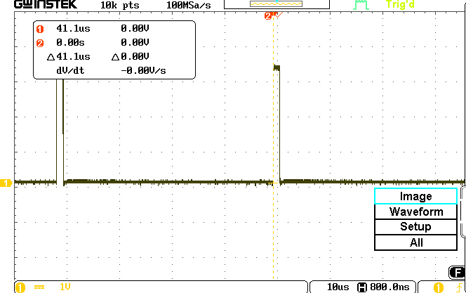
I have used the following program to produce continuous pulses on a Smart Pin (#20). Is that what this mode does? I expected to see a triangular waveform. Changing the X- and Y-register values changes the pulse width and the frame period. Why the word "triangle" in the mode title? What is the particular use or application for this type of PWM? I plan to add more details in the documentation for the Smart-Pin modes and want to understand what they do. (I use the default system-clock frequency for simplicity.) The attached scope images show a logic-1 time of 1.29 usec and a period of 41.1 usec for the settings in the code. Thanks. --Jon
CON
               
dat
	org	 0               
	dirl     #20			'Setup Smart-Pin at P20
       	wrpin    NCO_Config,    #20	'Set configuration for PWM Triangle mode
       	wxpin    X_RegData,     #20	'Set base period at 1 usec (25 MHz/#25)
       	dirh     #20			'Finished setup       
	wypin	 Y_RegData,	#20

.myloop		nop			
		jmp	#.myloop	'Program waits forever

NCO_Config	long	%0000_0000_000_00000_00000000_01_01000_0
Y_RegData	long	$0000_0010	
X_RegData	long	$0200_0001	
664 x 420 - 17K
664 x 417 - 17K

Comments

  • Both PWM modes work by continually comparing the configured pulse width against an internally generated waveform. The triangle mode compares against a triangle wave, the other one against a sawtooth wave. The result of the comparison is output on the pin.
  • So the DAC creates a continuous waveform and an analog comparator determines when to start and stop the logic-1 pulse. Got it. We see the pulses but not the triangular signal. Some research I just did provided answers to why designers might choose this mode but that goes beyond the "how to set up and use this mode." Thanks for help understanding this mode. --Jon
  • jmgjmg Posts: 15,145
    JonTitus wrote: »
    So the DAC creates a continuous waveform and an analog comparator determines when to start and stop the logic-1 pulse. Got it. We see the pulses but not the triangular signal. Some research I just did provided answers to why designers might choose this mode but that goes beyond the "how to set up and use this mode." Thanks for help understanding this mode. --Jon

    Not quite, the triangle is an Up/Down counter whose value plots like a staircase triangle, hence the name. There is no DAC/comp.
    Simpler PWM uses a UP counter only, and that value plots like a staircase sawtooth.
    A sawtooth PWM means all trailing edges are at the same time, whilst triangle allows multiple PWMs to have time-separated edges, permitting user controlled dead times on all edges.
    MOSFET Bridge power drivers prefer to turn off one mosfet, then allow some ns before they turn on the opposing mosfet. PWM Triangle allows that.
  • The description for the PWM Triangle Smart-Pin mode notes:
    At each base period, the captured [PWM] value is compared to the counter. If it is equal or greater, a high is output. If it is less a low is output.

    Does the word "it" refer to the counter count or to the captured value (register Y)? --Jon
  • Got it. No DAC, just an up-down counter. Thanks.
  • JonnyMacJonnyMac Posts: 8,924
    edited 2020-05-28 17:16
    I created a couple simple PWM objects for an upcoming Nuts & Volts article. The first is DMX-compatible (for LEDs), the other for servo control. I tried to document them in a way that helps the user understand how the PWM mode works.

    Edit: Fixed small error in jm_servo.spin2
  • Thanks, Jon.
  • Just found a small gotcha in the jm_servo.spin2 program: You can write in microseconds but it's not saving the correct angle. That's fixed now in the post above.
  • OK, thanks, Jon. Do you think the attached diagram in the documentation for Smart Pins would help people better understand the PWM-Triangle mode? Feel free to offer suggestions or note corrections. Cheers. --Jon
    4344 x 2573 - 296K
  • JonnyMacJonnyMac Posts: 8,924
    edited 2020-05-29 01:37
    I do in fact think it's helpful because I did something similar while working on my article (I decided to skip triangle mode so I didn't include the diagram). For clarity, you may want to generalize the values instead of using specific numbers.

    I am very visual person, so I use colors and overlay elements. Note that this diagram is not annotated, but you will see what I mean. It is deliberately setup to show the difference in the two modes given the same input values. The 'scope traces are from these values.
    pub main() | x, y
    
      ' 1000 Hz pwm @ 30% dc
    
      x.word[0] := (clkfreq / 1000) / 100                           ' sys ticks per unit
      x.word[1] := 100                                              ' frame units
      y := 30                                                       ' setting (dc = y/x.word[1])
    
      ' start pwm outputs
    
      pinstart(32, P_OE | P_PWM_SAWTOOTH, x, y)
      pinstart(33, P_OE | P_PWM_TRIANGLE, x, y)
    

    Edit: I decided to annotate my graphic using notation similar to Jon's.


    800 x 965 - 80K
    800 x 480 - 22K
  • Roy ElthamRoy Eltham Posts: 2,996
    edited 2020-05-28 23:42
    Very nice illustration of them Jon!

    Edit: ( both of you I guess :) )
  • Thanks. A bit of fun with Inkscape -- one of my favorite tools. Last weekend I made custom whiskey glasses for friends by creating stencils in Inkscape which were cut on a vinyl cutter. I've also used it to make specific shapes for laser cutting, and even oddly-shaped for PCBs (usually movie props or costume elements). It's x-platform, easy to learn, and you certainly can't beat the price. :smiley:
  • Nicely done, Jon. Thank you. I like diagrams, circuit schematics, flow charts, and charts, too. The medical cut-away charts in doctors' offices are always interesting and make waiting tolerable. I'll look at Inkscape for my Mac. Perhaps Parallax will consider using color drawings in the Propeller-2 documentation. Typically I create line drawings with the ExpressPCB schematic-capture program.
    The numbers I used in the figure came from a short program that I'll use as an example so people can relate the register information to the timing. Cheers. --Jon
  • jmgjmg Posts: 15,145
    The best illustrated example of Triangle PWM would come from showing 2 or more outputs generating PWM.
    IIRC Chip made it so you can config 2,3,6, etc PWMs and then a single start has all counters in sync from then on.
  • The medical cut-away charts in doctors' offices are always interesting and make waiting tolerable.
    Thankfully, I don't have to go to the doctor often, but that is the best part of the visit.
Sign In or Register to comment.