Shop OBEX P1 Docs P2 Docs Learn Events
Can't help it, must hack - a radio controlled clock — Parallax Forums

Can't help it, must hack - a radio controlled clock

ErlendErlend Posts: 612
edited 2020-05-05 14:34 in General Discussion
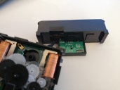
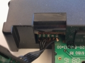
I am many decades old, but still I love to dismantle electronic stuff once in a while. For a long time I have toyed with the idea to interface the Propeller with a radio clock receiver. Finally the clock on the wall fell down and broke - minutes later I got it opened and found the (DCF77) receiver unit which is connected to the clockwork electronics. 5 wires connect the two, named VDD, RF, GND, AGC, PON. I am guessing Voltage, Time signal, Ground, Automatic Gain Control, Power on. Regards the latter, these clocks run on a single AA, so the receiver is only switched on once in a while. Why AGC is brought out I have no idea. AGC could also mean something different.
Next step would be to disconnect the clockwork, feed 1.4V VDD to the receiver, hook up a scope to the RF, and see what happens when PON is tied to +

Anyone done this before me?
3968 x 2976 - 2M
3968 x 2976 - 3M

Comments

  • The time signal is probably pulse coded similar to WWVB in the US. These things are kind of iffy. I looked hard at putting a WWVB receiver in the Nixie clock I built a few years ago, but couldn't find a receiver module on the market. They had all been removed due to format changes that made them inoperative. Nowadays the new hotness is to use NTP over wifi, easily done with an ESP8266 and one of hundreds of open NTP servers out there. It's much more reliable if you have wifi anyway, although it uses a lot more power when the module is on. In much of the US WWVB only works at night, which makes debugging it kind of tricky.
  • localroger wrote: »
    The time signal is probably pulse coded similar to WWVB in the US. These things are kind of iffy. I looked hard at putting a WWVB receiver in the Nixie clock I built a few years ago, but couldn't find a receiver module on the market. They had all been removed due to format changes that made them inoperative. Nowadays the new hotness is to use NTP over wifi, easily done with an ESP8266 and one of hundreds of open NTP servers out there. It's much more reliable if you have wifi anyway, although it uses a lot more power when the module is on. In much of the US WWVB only works at night, which makes debugging it kind of tricky.

    If it's DCF77 then there is a pulse every second, 100 or 200 ms. 100ms is 0, 200ms is 1. The full time/date is encoded in one minute (59 pulses). Second #59 has no pulse. IRC there is also a checksum and some status bits (DST active (CET/CEST), and DST change by end of the hour, which antenna is in use). Some years ago I did the decoding with prop. Would have to dig in my archives.
  • localroger,

    WWVB can be used to calibrate devices since it's "NIST-traceable".
  • It is a DCF77, and I know how the signalling works. I was more wondering about the hardware connection than the 'protocol'. And yes, there are better ways to get the time synch, but as I said the clock fell down from the wall...
  • ceptimusceptimus Posts: 135
    edited 2020-05-06 16:38
    Andreas Spiess has shown how to do it, both with a Raspberry Pi, and an ESP32

    https://youtu.be/r2UAmBLBBRM

    https://youtu.be/6SHGAEhnsYk

    I made one using a Raspberry Pi Zero W and a ferrite rod from an old transistor radio. I put it in a 3D-printed case with the ferrite rod sticking out (because it's longer than the Pi Zero PCB). Working the RF stage from the Pi's 3.3V it has a range of a few metres. I tried it on the 5V supply and it worked all over my house. I switched back to the 3.3V because I don't want to interfere with any radio clocks that my neighbours may have.

    radioClockTx.jpg

    I can connect to the Pi using SSH to set the time of my clocks - no need for the Pi to have any wired connections other than power.
    1024 x 1436 - 208K
  • Thierry Egger make it in spin

    I attache it
  • LtechLtech Posts: 380
    edited 2020-05-06 17:07
    Didn't upload with Safari, I use Firefox here....
  • Thanks, nice to be able to use the P1 as a local DCF tx - makes it easier to find out how the receiver board works. I still need good advice on what to do with the signals RF, AGC, and PON, though. Still have no success getting a signal from the thing.
  • ErlendErlend Posts: 612
    edited 2020-05-07 19:37
    I finally googled my way into some heplful info. AGC is optional and can be left unconnected, PON is what I assumed but should be tied low, not high, to enable the receiver, and RF is the time signal (have not dechiffered the acronym). On the scope I can see the DCF77 time code signal coming in every minute. Next step is to levelconvert and feed the signal into P1 and decode it. I am surprised that I am getting a strong signal this far away from the transmitter, even being down in the basement, but then I read they planned to upgrade the transmitter power this year - so that is maybe what has now happened.
Sign In or Register to comment.