

Faster SPI Bus Transfers
 cgracey
Posts: 14,323
cgracey
Posts: 14,323
I'm working on the 2nd-stage flash booter for application launching. The first thing to sort out is how to quickly program the flash, so the user doesn't have to wait long. Then, the loader which executes on reset must pull the data from the flash into memory very quickly.
The regular way of looping to get the next data bit, outputting it, raising the clock, and lowering the clock is quite slow. I've been working out how to speed it up. This code runs off the RCFAST oscillator at boot, which is always over 20MHz and usually ~24MHz. The oscillator is designed to not drop below 20MHz, worst-case, to support auto-baud serial connections of up to 2Mbaud.
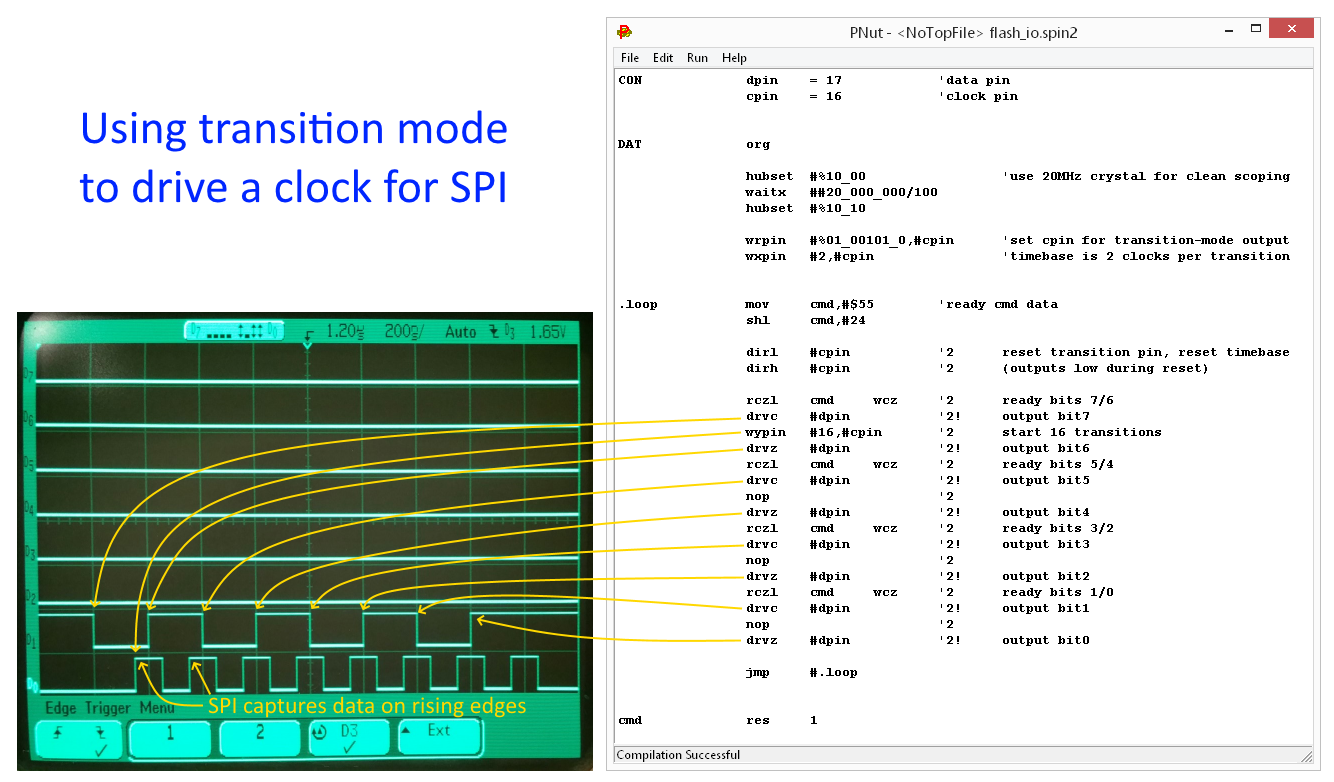
As a first pass, I used the smart pin mode which outputs timed transitions to generate the SPI clock. I then output the data manually in software. I was lamenting that I didn't make an instruction to just shift a register and output the bit to some pin. That would have made things really easy and fast. We don't have that, but I realized that the RCZL instruction, which rotates a register two bits left and puts the bits into C and Z could save some time. The transition mode can then generate the clock in the background while my code outputs the data bit stream. It works really nicely.
Here's the code:
And see the picture of what it does...
The regular way of looping to get the next data bit, outputting it, raising the clock, and lowering the clock is quite slow. I've been working out how to speed it up. This code runs off the RCFAST oscillator at boot, which is always over 20MHz and usually ~24MHz. The oscillator is designed to not drop below 20MHz, worst-case, to support auto-baud serial connections of up to 2Mbaud.
As a first pass, I used the smart pin mode which outputs timed transitions to generate the SPI clock. I then output the data manually in software. I was lamenting that I didn't make an instruction to just shift a register and output the bit to some pin. That would have made things really easy and fast. We don't have that, but I realized that the RCZL instruction, which rotates a register two bits left and puts the bits into C and Z could save some time. The transition mode can then generate the clock in the background while my code outputs the data bit stream. It works really nicely.
Here's the code:
CON		dpin	= 17		'data pin
		cpin	= 16		'clock pin


DAT		org

		hubset	#%10_00			'use 20MHz crystal for clean scoping
		waitx	##20_000_000/100
		hubset	#%10_10

		wrpin	#%01_00101_0,#cpin	'set cpin for transition-mode output
		wxpin	#2,#cpin		'timebase is 2 clocks per transition


.loop		mov	cmd,#$55	'ready cmd data
		shl	cmd,#24

		dirl	#cpin		'2	reset transition pin, reset timebase
		dirh	#cpin		'2	(outputs low during reset)

		rczl	cmd	wcz	'2	ready bits 7/6
		drvc	#dpin		'2!	output bit7
		wypin	#16,#cpin	'2	start 16 transitions
		drvz	#dpin		'2!	output bit6
		rczl	cmd	wcz	'2	ready bits 5/4
		drvc	#dpin		'2!	output bit5
		nop			'2
		drvz	#dpin		'2!	output bit4
		rczl	cmd	wcz	'2	ready bits 3/2
		drvc	#dpin		'2!	output bit3
		nop			'2
		drvz	#dpin		'2!	output bit2
		rczl	cmd	wcz	'2	ready bits 1/0
		drvc	#dpin		'2!	output bit1
		nop			'2
		drvz	#dpin		'2!	output bit0

		jmp	#.loop


cmd		res	1
And see the picture of what it does...
1334 x 782 - 433K
Comments
That said, I never got round to testing it on a real SPI device. I think it was still RevA silicon.
I remember Peter had asked if it was worth using the smartpins at all and I'd initially said not really.
I just got sysclock/2 working and it's mind-blowingly simple. Sometimes things just work out. It was accidental that it could work so perfectly. Just a minute...
This means that running from RCFAST, not counting flash erase and program delays, you could load 512KB into the flash in just 400ms! No need to even use the crystal/PLL, which could actually make the software much more complicated.
In this program, I'm outputting a whole 32 bits, which is what the loader will be doing to program the flash. Note that the data changes on the falling clock, so that it's stable during the rising clock. This will run SPI at over 10MHz using RCFAST:
Here's a picture of it running...
For reading back, it's easier to use a smartpin though.
There can't be a faster or a simpler way to do this. It's miraculous that the timing aligned so well. Note that it's ONE clock different, as needed, due to an extra clock delay in the streamer design.
So, this wraps up how to do fast SPI output. Now, I've got to see about SPI input using the same ideas, but with the streamer inputting a pin. Not sure how that timing will be.
Yes, I had to cover for that in the first example in the initial post, but when you set the timebase to ONE clock, you don't have that problem because its metronome ticks on every clock. The only way you could screw it up would be issuing another command before it finishes the current command, causing it to toggle some odd number of times, leaving it in the opposite state you intended. We have provision for that in the WAITXFI.
Streamer for reading SPI data does work but it's a lot of trial and error to align timing. Here's an example HyperRAM snippet I was using for testing various questions:
Total smartpins = 64 1111111111111111111111111111111111111111111111111111111111111111 Rev B silicon. Sysclock 30.0000 MHz Experimental HyperRAM Copying =============================== COMP CYCLES HR_DIV HR_WRITE HR_READ BASEPIN 0 0 2 a0aec350 e0aec350 16 ------------------------------------------------------------------------------------------ | COUNT OF BIT ERRORS | |------------------------------------------------------------------------------------------| | | Compensations | | XMUL | 0 1 2 3 4 5 6 7 8 9 | |--------|---------------------------------------------------------------------------------| 30 | 200018 200325 199928 200015 0 0 200253 200622 199254 200581 31 | 200090 199832 200474 199864 0 0 200159 199431 200548 200017 32 | 200425 200043 199813 200109 0 0 199501 199690 199845 200702 33 | 200020 199416 200487 200104 0 0 200089 200137 200576 200019 34 | 199649 199906 200596 199515 0 0 199405 199784 200364 200210 35 | 199931 199900 200788 200063 0 0 199641 199283 200275 199642 36 | 200126 200549 199753 200124 0 0 200015 199748 199960 199838 37 | 199821 199890 199799 199428 0 0 199918 199376 199827 200335 38 | 200003 200160 199577 200162 0 0 200007 199878 199820 199814 39 | 200386 199866 199471 200518 0 0 200229 199485 200011 199722 40 | 200511 199398 199609 200121 0 0 200378 199860 200871 199878 41 | 199954 200027 199957 200270 0 0 200033 199938 199374 199936 42 | 199729 200026 199757 199645 0 0 200251 200442 200373 200024 43 | 199480 200365 200539 200104 0 0 199270 200097 200005 200276 ...I'm thinking that to develop the SPI input, I'll have another cog output the same clock stream, but with output data. I'll then tune the inputting cog, which is outputting a sync'd clock stream, from the other cog's output data.
Total smartpins = 64 1111111111111111111111111111111111111111111111111111111111111111 Rev B silicon. Sysclock 30.0000 MHz Experimental HyperRAM Copying =============================== COMP CYCLES HR_DIV HR_WRITE HR_READ BASEPIN 0 0 2 a0aec350 e0aec350 16 ------------------------------------------------------------------------------------------ | COUNT OF BIT ERRORS | |------------------------------------------------------------------------------------------| | | Compensations | | XMUL | 0 1 2 3 4 5 6 7 8 9 | |--------|---------------------------------------------------------------------------------| 30 | 199833 199476 199892 199530 0 0 200077 199930 200097 199910 31 | 200009 199815 199923 200484 0 0 200585 199816 200012 200372 32 | 200495 199790 200225 200000 0 0 200354 200088 200065 199856 33 | 199503 200532 199997 200316 0 0 199878 199544 200850 199484 34 | 200215 200496 199747 200377 0 0 199977 199996 199886 199839 35 | 200049 200043 199827 199966 0 0 199860 199573 200392 199495 36 | 200175 200151 199593 199715 0 0 200056 200365 200048 199972 37 | 199638 199903 200351 200225 0 0 200190 199570 199982 199609 38 | 200324 200184 200235 199948 0 0 200632 200126 200050 199687 39 | 199828 199783 200911 200504 0 0 199827 200510 200011 199989 40 | 199753 199872 199446 199663 0 0 199963 199755 199548 199905 41 | 199589 200101 199793 199948 0 0 200188 199853 200245 200165 42 | 200215 200001 200074 199601 0 0 200095 200136 199981 199255 ...When the SPI device outputs, it updates its data output after the falling edge of the clock. I'll have to make my simulator work like this.
I'm now thinking that flash programming should happen DURING the download, so that you don't suffer the download time, then have the programming time on top of it. The bigger the download to flash, the more it will benefit from download/programming overlap.
Thanks, Evanh. That data is really interesting. Sheesh.... What do we do? Is it practical to try to adjust dynamically to these shifts?
EDIT: The board layout has a large impact on the slew rate. That was proven with the revA Eval boards where the SD slot and EEPROM were placed on the opposite side of the board from the I/O header and prop2 pins. The max SPI clock was really bad there.
He was initially only talking about bit-bashing methods.
Smartpins can't improve the read slew rate issue, they're not not true clock inputs.
> Smartpins can't improve the read slew rate issue, they're not not true clock inputs.
Not to derail the topic, but it seems reasonable that most people coming to the P2 will gravitate towards those pin modes first. I get that they are not the fastest possible solution in all cases, but the fact that Chip seemed to skip over them as a possible solution makes me concerned about their actual usefulness. I'm particularly surprised that they're not being considered for the receive mode, where it seems they should be the ideal choice here.
Here's the output for the same config, write timings, but with the unmodified hyperRAM board fitted:
    COMP  CYCLES   HR_DIV  HR_WRITE    HR_READ  BASEPIN
       0       0       2   a0aec350   e0aec350      16
 ------------------------------------------------------------------------------------------
|                                      COUNT OF BIT ERRORS                                 |
|------------------------------------------------------------------------------------------|
|        |                                 Compensations                                   |
|   XMUL |       0       1       2       3       4       5       6       7       8       9 |
|--------|---------------------------------------------------------------------------------|
      30 |  199989  197827  199665  120247       0   80158  199466  199560  200175  199492
      31 |  199698  198623  200400  119343       0   79878  200656  199841  200318  200168
      32 |  200224  198486  200006  120221       0   79984  199874  199616  199543  199877
      33 |  199739  198849  200309  119626       0   80254  199900  200038  199516  200405
      34 |  200279  198725  199441  119604       0   80181  199502  200343  199657  199785
      35 |  200024  198217  200105  120474       0   79568  200594  200360  199700  200017
      36 |  199997  198479  199730  119457       0   80041  200091  200052  199947  199885
      37 |  200328  197861  199471  119789       0   80383  200050  200324  199848  199994
      38 |  200257  198228  200124  119661       0   79991  199869  200074  199925  199705
      39 |  199935  198333  199471  119520       0   79915  199892  199430  199939  199881
      40 |  199896  197917  199842  119358       0   80709  199921  200193  199817  200103
...
Note, only has one good compensation column. Problem with this is when attempting to go to full DDR capabilities of the hyperRAM the column with zero errors vanishes entirely.Just that the Prop2 can go so fast, and is so easy to push it there, that there is other potential issues that could never affect the Prop1. Many other micros didn't have the speed in the past either. It's all a little new in some ways.
Then, the other half of dealing with this is latching the shifted data into a buffer without any potential glitches between the two clocks. It shouldn't be a huge issue given the ratio between shifting and latching. Similar to solving the sysclock PLL mode change.
The smart pin serial synchronous output mode, on the other hand, inputs the clock and outputs the data, so it suffers turn-around delays, making sysclock/2 impossible.
First, you need to set up a smart pin to generate the clock signal and set the streamer rate:
To output a value:
To output from hub memory:
To input to hub memory:
That's all there is to it!
Here is a test program that I developed this with. There are two cog programs. One outputs data and the other receives and verifies data. They time-align their clock outputs so that you can know that the receiver (clock on P18) is aligned with the transmitter (clock on P16). The transmitter outputs data on P17 and the receiver inputs from P17. It's doing 32 bits at a time. In the hub-transfer modes, you could do up to 8191 bytes at a time, unless you could use $FFFF for infinite and then do an XSTOP at the right time.
Reading back through the docs, I now see the two-clock delay comment. I guess for slaves that can read on the rising edge, I suppose you could get down to sysclock/4 (so that output is effective written on the falling edge). But, other than that, sysclock/8 (or maybe sysclock/6 for slow-enough clock settings) is the best you can achieve?
I don't know. This gets so complex that writing code and looking at it on the scope is the best way to know the timing.
The smart pin synchronous serial input suffers from the turn-around delays. We added another flop on each input on Rev B silicon, and I don't think I updated the docs for that mode.
If you can control the clock, you can do much better than the smart pin synchronous input mode. If you are waiting for an external clock, you can't improve its function. There are just a lot of register stages.
Maybe even 4-bit SD bus? Although the way the SD card is connected for booting complicates this.