Here's the Blackman-Harris window produced in a spreadsheet - what's the best way of applying it to a signal in the 32 bit integer environment of the P2?
A question of scaling the function up? Large enough to retain as much precision as possible, consistent with avoiding overflow when multiplying the signal, sample by sample.
The scaled window is a constant, so it's a DATA block to be loaded into a buffer on start up, I guess.
@bob_g4bby said:
Here's the Blackman-Harris window produced in a spreadsheet - what's the best way of applying it to a signal in the 32 bit integer environment of the P2?
The best you could do with the CORDIC QMUL is one sample every 16 cycles. Your Blackman-Harris window length is 1024 samples with 512 different values so the obvious place to store them is LUT RAM. Will successive windows overlap by 512 samples?
Data could be read from hub RAM using RFLONG with 256 results, say, stored temporarily in reg RAM then written back later using fast block write. Alternatively, do fast block read to pre-load 256 samples in reg RAM and write results directly to hub RAM using WFLONG. Or use RFLONG and WRLONG (but the former might stall the later) with no intermediate storage in reg RAM if timing allows for that.
Good idea, LUT ram is the best place and like you say, the window is symmetric, so storing half of it is enough.
Yes, the FFT fast convolution filtering that comprises the software defined radio main filter does include an overlap-add feature - see attached pdf
I've got the dsp functions going quite fast as follows:-
1. Move 16 iq pairs from the input buffer in hub ram into a small register array using SETQ #31, RDLONG regarray, ptra++. This takes 1 cycle per long - see here.
2. Preload the cordic engine with 8 inputs from the register array.
3. Read result back from cordic into register array and load the cordic engine with another input - do this 8 times
4. Read the last 8 results from the cordic engine back into register array. For many dsp functions (2) to (4) results in around 9 cycles per cordic result
5. Move 16 iq pairs from register array back to the output buffer in hub ram. This again takes 1 cycle per long.
6. Repeat (1) to (5) 64 times for the whole buffer
Here's an example, with timing based on Chip's example:-
The NOP's between the QVECTOR's are not necessary, I think. Re window coefficients in LUT RAM, the 3 cycle RDLUT could be an issue for CORDIC pipelining and it might be quicker to keep some of them in reg RAM and swap them in and out as required.
@bob_g4bby said:
That's very interesting, I'll take the nops out, thanks both! RDLUT issue noted too.
You could put up to 3*7=21 normally two-cycle but effectively zero-cycle instructions between 1st and 8th QVECTOR. I'll be interested to see your windowing code, whenever that may be.
I made a huge breakthrough on the bit-reversal that is a usual part of doing an FFT. The bit-reversal code in the last update took 160uS. This new code does digit-reversal in 50uS, when combined with other parts of the FFT.
Radix-4 FFT need digit reversal instead of bit reversal. For radix-4, digits are 2 bits. Thankfully with the P2's bit shuffling instructions it's only 3 extra instructions. This is still a lot of instructions for reading a single sample.
Let's look at what the digit reversal does.
The XOR trick I used previously won't work for addressing data because we can't assume that the arrays are aligned to their size. The carries would happen at different times depending on the array starting address. If we look at the differences between addresses we see that it follows a regular pattern. The current address can be adjusted to the next address with only a single ADD. After 16 samples there are additional bits rolling over. It's not a big deal. We just need to run the full digit reversal calculation to deal with this. The same method could be applied to bit-reversal as well, but will require more unique step sizes.
Of course the FIFO takes time to read from the hub. This wait time can be filled with the next address calculation or butterfly operations.
Combined with the greater computational efficiency of the radix-4 FFT, a complete 1024 point transform happens in 870uS. That is an unbelievable 25% reduction from the previous 1175uS. All times at 160MHz.
@SaucySoliton said:
I made a huge breakthrough on the bit-reversal that is a usual part of doing an FFT. The bit-reversal code in the last update took 160uS. This new code does digit-reversal in 50uS, when combined with other parts of the FFT.
Combined with the greater computational efficiency of the radix-4 FFT, a complete 1024 point transform happens in 870uS. That is an unbelievable 25% reduction from the previous 1175uS. All times at 160MHz.
Good work!
Re your code:
setnib .dit4ret,#%0000,#7 ' set condition to _ret_
'...
setnib .dit4ret,#%1111,#7 ' set condition to always
changing the instruction prefix from always to _ret_ is an interesting way of converting plain code into a subroutine. The drawback is that another instruction is needed to reverse the change. Quite often in skip sequences I create a routine by duplicating an instruction but with a _ret_ prefix and which is always skipped. This adds only one long although it does require skipping to be active.
Thanks!
The call/return happens 64 times. It runs inline 64*3 = 192 times. The called section is 154 instructions so it would be nice to not duplicate that.
if_c ret ' would be 2 cycles if not returning, 4 cycles if returning
_ret_ sub ay,cy ' 0 cycles if not returning, 2 cycles if returning
Due to hub and cordic alignment saving 2 cycles might cut 8 cycles off the loop.
I came up with another way of trying not to branch within the loop. The return address for djnz can be patched return to different locations.
testb p_fft_flags,#NOBR_BIT wc
' patch the loop return location to reduce time penalty for
' selecting which read method to use.
' only 3uS difference.
if_c sets .first_loop_end,#(.seqread_dit - .first_loop_end -1 )&$1ff
if_nc sets .first_loop_end,#(.randread_reorder - .first_loop_end -1)&$1ff
.first_loop
if_nc jmp #.randread_reorder
.seqread_dit setq #32-1
rdlong ax,ptra++
jmp #.bfly1
.randread_reorder
... ' this code mutually exclusive with .seqread
.bfly1
... ' this code always runs
.first_loop_end djnz flight_count,#.first_loop
This isn't in the uploaded code. After unrolling the randread function, most of bfly1 became dispersed between fifo reads. It was simpler just to go to 2 separate loops.
That's a very worthwhile gain in performance - can't wait to adopt your code. I've been reviewing fft fast convolution filtering and I've made spin code that creates the required bandpass filter impulse response. A small windows based software radio has been modified to supply an analogue iq signal which is converted to 48ks/s signal buffers in the P2 via an HDaudio kit. Spin Tools writes a single debug scope window fast enough to keep up with the signal, which is really useful. I've just written an 8x knobs driver to control signal settings later on.
Much appreciated, bob
Fair warning, the new library might invert your spectrum. I think the issue can be corrected by inverting the IFFT flag from how it used to be.
The new library does not modify the input data array. That might save some time. It think it's possible to modify the input section to read directly from a circular buffer.
For FFT filtering, I still think it is possible to filter without doing any bit reversals. It would go like this:
time data -> DIF FFT -> digit reversed frequency data -> DIT IFFT -> time data
The transformed data would not even need to be written to hub ram. The filter coefficients could be digit reversed once after they are generated. However, given the massive improvements to the bit reversal section I'm not sure it's worth trying to do that.
I found a page that suggested the Inverse FFT could be computed by reversing most of the input array. The new input section could accommodate that at minimal cost. It didn't work quite right. It looked like a bad window function that allowed energy from the peaks to spread across the spectrum. This doesn't show what I saw but it's a good explanation. https://www.katjaas.nl/inverseFFT/inverseFFT.html The ARRL handbook did not mention the reversal method, maybe they know. So, back to conjugating the input and output data.
@SaucySoliton , Here are two fft tests. 'fft test 1.spin2' uses the inline fft, 'fft test 2.spin2' uses the radix 4 fft. Test 1 shows a swept sinewave and the resulting spectrum - looks normal. Test 2, the spectrum bobs up and down in an unexpected way. Have I misused the radix 4 method, or is there a bug? I notice the spectrum inversion - I've adjusted the debug PLOT so both spectrums appear normal - 0Hz on the left. Please run both tests under Spin Tools with debug enabled.
Cheers, Bob
I've not been able to get spin tools to work. I did build the tests with pnut-ts and run them in pnut-term-ts. I did see the amplitude change. The reason for that may be that the scope is showing the input to xytopol instead of the output.
I've quietly uploaded a mixed-radix fft to the obex. The mixed-radix version adds a radix-2 stage onto the radix-4 fft in the case the size is not a power of 4. If you are using a 1024 there no reason to change.
Also I wrote a new fft accuracy tester in spin2. It's in the obex. The fft libraries are tested against a discrete Fourier transform which still uses the cordic. The DFT is simple enough that it's unlikely I made a mistake with it, plus the results match the other FFT functions. With the exception of the phase rotation direction issue. If you are concerned with only the magnitudes of a real-input signal, as was the original use of Chip's code posted here, there is no difference. My newer libraries are designed to use either direction rotation as that is the fastest way to compute IFFT.
"the scope is showing the input to xytopol instead of the output" - phew! sorry for ringing a false alarm bell - having fixed my bug, it's identical to the radix 2 again. Your test against DFT reminds me that some of the railway signalling kit I EMC tested had two identical microprocessors in them which had to cooperate to control the railway. The two channels had to employ two different versions of firmware using only certain instructions in each, so that there was little chance of a common mode bug getting through. If they ever disagreed, they would blow an internal fuse!
I've started timing the dsp code sections and all looks well - 48ksample/s dsp based on in-line pasm methods is a viable technique and I'll use the radix-4 fft from now on. Spin2 byte interpreter speed has been a pleasant surprise - I imagined it to be far slower than Taqoz forth, but it isn't and occupies far less space.
I thought maybe I could put my LameStation to work for a spectrum analysis project. Would just need an FFT for P1.
PASM2 isn't that different from PASM, we just need to replace the CORDIC. How about with a software CORDIC? After 31 cordic stages the shifted terms will round to zero, as well as the angle.
I think it can be done in 7 instructions per stage if unrolled. The P1 will take about 210 instructions or 840 clocks to replicate QROTATE without any scaling. I figured I could just use unscaled cordic operations and scale it all at the end.
A QROTATE needs 8 clock cycles on the P2, if there is enough other work to fill the latency. P2 is 100x+ faster on a per cycle basis. With P2's higher clock rate it's 200-400x faster. So depending on the instruction mix the P1 FFT would be somewhere between 4 and 200 times slower. Thus a 1024 FFT could take as long as 176mS.


Comments
Here's the Blackman-Harris window produced in a spreadsheet - what's the best way of applying it to a signal in the 32 bit integer environment of the P2?
A question of scaling the function up? Large enough to retain as much precision as possible, consistent with avoiding overflow when multiplying the signal, sample by sample.
The scaled window is a constant, so it's a DATA block to be loaded into a buffer on start up, I guess.
The best you could do with the CORDIC QMUL is one sample every 16 cycles. Your Blackman-Harris window length is 1024 samples with 512 different values so the obvious place to store them is LUT RAM. Will successive windows overlap by 512 samples?
Data could be read from hub RAM using RFLONG with 256 results, say, stored temporarily in reg RAM then written back later using fast block write. Alternatively, do fast block read to pre-load 256 samples in reg RAM and write results directly to hub RAM using WFLONG. Or use RFLONG and WRLONG (but the former might stall the later) with no intermediate storage in reg RAM if timing allows for that.
Good idea, LUT ram is the best place and like you say, the window is symmetric, so storing half of it is enough.
Yes, the FFT fast convolution filtering that comprises the software defined radio main filter does include an overlap-add feature - see attached pdf
I've got the dsp functions going quite fast as follows:-
1. Move 16 iq pairs from the input buffer in hub ram into a small register array using SETQ #31, RDLONG regarray, ptra++. This takes 1 cycle per long - see here.
2. Preload the cordic engine with 8 inputs from the register array.
3. Read result back from cordic into register array and load the cordic engine with another input - do this 8 times
4. Read the last 8 results from the cordic engine back into register array. For many dsp functions (2) to (4) results in around 9 cycles per cordic result
5. Move 16 iq pairs from register array back to the output buffer in hub ram. This again takes 1 cycle per long.
6. Repeat (1) to (5) 64 times for the whole buffer
Here's an example, with timing based on Chip's example:-
' convert x,y (cartesian) samples in buffin to magnitude, angle (polar) samples in buffout - optionally, buffout can be the same as buffin ' at 320MHz clock, runs about 56.1uS ' result stored as mag1, real1, mag2, real2 etc. pub xytopol(buffin, buffout) | counter org push ptra mov ptra, buffin mov ptrb, buffout mov counter, #(sigbuffsize/16) xypol1 setq #31 rdlong array, ptra++ qvector array, array+1 nop qvector array+2, array+3 nop qvector array+4, array+5 nop qvector array+6, array+7 nop qvector array+8, array+9 nop qvector array+10, array+11 nop qvector array+12, array+13 nop qvector array+14, array+15 getqx array getqy array+1 nop qvector array+16, array+17 getqx array+2 getqy array+3 nop qvector array+18, array+19 getqx array+4 getqy array+5 nop qvector array+20, array+21 getqx array+6 getqy array+7 nop qvector array+22, array+23 getqx array+8 getqy array+9 nop qvector array+24, array+25 getqx array+10 getqy array+11 nop qvector array+26, array+27 getqx array+12 getqy array+13 nop qvector array+28, array+29 getqx array+14 getqy array+15 nop qvector array+30, array+31 getqx array+16 getqy array+17 getqx array+18 getqy array+19 getqx array+20 getqy array+21 getqx array+22 getqy array+23 getqx array+24 getqy array+25 getqx array+26 getqy array+27 getqx array+28 getqy array+29 getqx array+30 getqy array+31 setq #31 wrlong array, ptrb++ djnz counter, #xypol1 pop ptra ret array res 32 endThe
NOP's between theQVECTOR's are not necessary, I think. Re window coefficients in LUT RAM, the 3 cycleRDLUTcould be an issue for CORDIC pipelining and it might be quicker to keep some of them in reg RAM and swap them in and out as required.Not needed. CORDIC ops automatically insert waitstates so they're spaced a multiple of 8 cycles apart
That's very interesting, I'll take the nops out, thanks both! RDLUT issue noted too.
You could put up to 3*7=21 normally two-cycle but effectively zero-cycle instructions between 1st and 8th
QVECTOR. I'll be interested to see your windowing code, whenever that may be.I made a huge breakthrough on the bit-reversal that is a usual part of doing an FFT. The bit-reversal code in the last update took 160uS. This new code does digit-reversal in 50uS, when combined with other parts of the FFT.
Radix-4 FFT need digit reversal instead of bit reversal. For radix-4, digits are 2 bits. Thankfully with the P2's bit shuffling instructions it's only 3 extra instructions. This is still a lot of instructions for reading a single sample.
        rdfast  c_8000,ptrr
        add     i1,#1
        mov     next_ptrr,i1
        splitw  next_ptrr  *
        rev     next_ptrr
        rol next_ptrr,shift  *
        mergew  next_ptrr  *
        shl      next_ptrr,#3
        add     next_ptrr,real_imag_ptr
        rflong  ax+A
        rflong  ay+A
Let's look at what the digit reversal does.
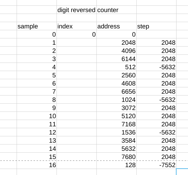
The XOR trick I used previously won't work for addressing data because we can't assume that the arrays are aligned to their size. The carries would happen at different times depending on the array starting address. If we look at the differences between addresses we see that it follows a regular pattern. The current address can be adjusted to the next address with only a single ADD. After 16 samples there are additional bits rolling over. It's not a big deal. We just need to run the full digit reversal calculation to deal with this. The same method could be applied to bit-reversal as well, but will require more unique step sizes.
Of course the FIFO takes time to read from the hub. This wait time can be filled with the next address calculation or butterfly operations.
Combined with the greater computational efficiency of the radix-4 FFT, a complete 1024 point transform happens in 870uS. That is an unbelievable 25% reduction from the previous 1175uS. All times at 160MHz.
Sorry, flexspin only right now.
Good work!
Re your code:
                setnib  .dit4ret,#%0000,#7    ' set condition to _ret_
'...
                setnib  .dit4ret,#%1111,#7    ' set condition to always
changing the instruction prefix from
alwaysto_ret_is an interesting way of converting plain code into a subroutine. The drawback is that another instruction is needed to reverse the change. Quite often in skip sequences I create a routine by duplicating an instruction but with a_ret_prefix and which is always skipped. This adds only one long although it does require skipping to be active.Thanks!
The call/return happens 64 times. It runs inline 64*3 = 192 times. The called section is 154 instructions so it would be nice to not duplicate that.
Due to hub and cordic alignment saving 2 cycles might cut 8 cycles off the loop.
I came up with another way of trying not to branch within the loop. The return address for djnz can be patched return to different locations.
            testb   p_fft_flags,#NOBR_BIT wc
        ' patch the loop return location to reduce time penalty for
        ' selecting which read method to use.
        ' only 3uS difference.
    if_c    sets    .first_loop_end,#(.seqread_dit - .first_loop_end -1 )&$1ff
    if_nc   sets    .first_loop_end,#(.randread_reorder - .first_loop_end -1)&$1ff
.first_loop
    if_nc   jmp #.randread_reorder


.seqread_dit    setq    #32-1
                rdlong  ax,ptra++
                jmp #.bfly1

.randread_reorder
...  ' this code mutually exclusive with .seqread
.bfly1
...  ' this code always runs
.first_loop_end djnz    flight_count,#.first_loop
This isn't in the uploaded code. After unrolling the randread function, most of bfly1 became dispersed between fifo reads. It was simpler just to go to 2 separate loops.
That's a very worthwhile gain in performance - can't wait to adopt your code. I've been reviewing fft fast convolution filtering and I've made spin code that creates the required bandpass filter impulse response. A small windows based software radio has been modified to supply an analogue iq signal which is converted to 48ks/s signal buffers in the P2 via an HDaudio kit. Spin Tools writes a single debug scope window fast enough to keep up with the signal, which is really useful. I've just written an 8x knobs driver to control signal settings later on.
Much appreciated, bob
https://obex.parallax.com/obex/fft-ifft/
Fair warning, the new library might invert your spectrum. I think the issue can be corrected by inverting the IFFT flag from how it used to be.
The new library does not modify the input data array. That might save some time. It think it's possible to modify the input section to read directly from a circular buffer.
For FFT filtering, I still think it is possible to filter without doing any bit reversals. It would go like this:
time data -> DIF FFT -> digit reversed frequency data -> DIT IFFT -> time data
The transformed data would not even need to be written to hub ram. The filter coefficients could be digit reversed once after they are generated. However, given the massive improvements to the bit reversal section I'm not sure it's worth trying to do that.
I found a page that suggested the Inverse FFT could be computed by reversing most of the input array. The new input section could accommodate that at minimal cost. It didn't work quite right. It looked like a bad window function that allowed energy from the peaks to spread across the spectrum. This doesn't show what I saw but it's a good explanation. https://www.katjaas.nl/inverseFFT/inverseFFT.html The ARRL handbook did not mention the reversal method, maybe they know. So, back to conjugating the input and output data.
Thinking about 2D fft on fft vs time for wake word identification …. This should help..
Think need to do on PC first to optimize .
Guess need to figure out how to do this kind of fixed point in C++
@SaucySoliton , Here are two fft tests. 'fft test 1.spin2' uses the inline fft, 'fft test 2.spin2' uses the radix 4 fft. Test 1 shows a swept sinewave and the resulting spectrum - looks normal. Test 2, the spectrum bobs up and down in an unexpected way. Have I misused the radix 4 method, or is there a bug? I notice the spectrum inversion - I've adjusted the debug PLOT so both spectrums appear normal - 0Hz on the left. Please run both tests under Spin Tools with debug enabled.
Cheers, Bob
I've not been able to get spin tools to work. I did build the tests with pnut-ts and run them in pnut-term-ts. I did see the amplitude change. The reason for that may be that the scope is showing the input to xytopol instead of the output.
I've quietly uploaded a mixed-radix fft to the obex. The mixed-radix version adds a radix-2 stage onto the radix-4 fft in the case the size is not a power of 4. If you are using a 1024 there no reason to change.
Also I wrote a new fft accuracy tester in spin2. It's in the obex. The fft libraries are tested against a discrete Fourier transform which still uses the cordic. The DFT is simple enough that it's unlikely I made a mistake with it, plus the results match the other FFT functions. With the exception of the phase rotation direction issue. If you are concerned with only the magnitudes of a real-input signal, as was the original use of Chip's code posted here, there is no difference. My newer libraries are designed to use either direction rotation as that is the fastest way to compute IFFT.
"the scope is showing the input to xytopol instead of the output" - phew! sorry for ringing a false alarm bell - having fixed my bug, it's identical to the radix 2 again. Your test against DFT reminds me that some of the railway signalling kit I EMC tested had two identical microprocessors in them which had to cooperate to control the railway. The two channels had to employ two different versions of firmware using only certain instructions in each, so that there was little chance of a common mode bug getting through. If they ever disagreed, they would blow an internal fuse!
I've started timing the dsp code sections and all looks well - 48ksample/s dsp based on in-line pasm methods is a viable technique and I'll use the radix-4 fft from now on. Spin2 byte interpreter speed has been a pleasant surprise - I imagined it to be far slower than Taqoz forth, but it isn't and occupies far less space.
Cheers, bob
I thought maybe I could put my LameStation to work for a spectrum analysis project. Would just need an FFT for P1.
PASM2 isn't that different from PASM, we just need to replace the CORDIC. How about with a software CORDIC? After 31 cordic stages the shifted terms will round to zero, as well as the angle.
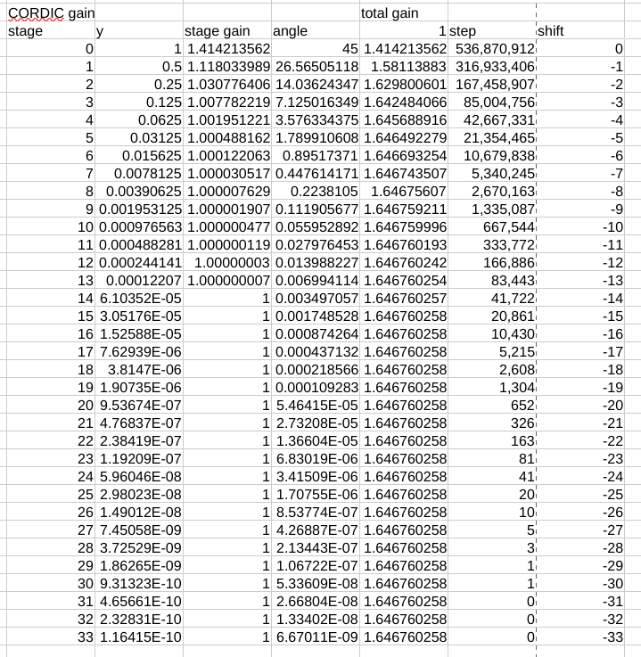
I think it can be done in 7 instructions per stage if unrolled. The P1 will take about 210 instructions or 840 clocks to replicate QROTATE without any scaling. I figured I could just use unscaled cordic operations and scale it all at the end.
A QROTATE needs 8 clock cycles on the P2, if there is enough other work to fill the latency. P2 is 100x+ faster on a per cycle basis. With P2's higher clock rate it's 200-400x faster. So depending on the instruction mix the P1 FFT would be somewhere between 4 and 200 times slower. Thus a 1024 FFT could take as long as 176mS.
Heater's FFT takes 25mS. https://forums.parallax.com/discussion/128292/heaters-fast-fourier-transform I'm glad I searched before writing any code.
In Chips speech synthesis for P1 he used a software cordic with very carefully chosen number of bits resolution.