Current measurements on the P2 Eval RevA
Hi,
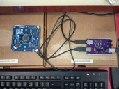
Today I've took the liberty to perform some current measurements on the P2Eval, while on idle, and then when programming and running the prime numbers calculator program (code available inside the attached zip file - thanks to ersmith for suggesting some improvements, BTW). As you can see, in the photo attached, the board was being supplied via its "PC USB" connector. The device on the right is the ITUSB1, a USB test switch that also has the capability of measuring current, besides connecting and disconnecting VBUS and data lines.
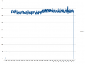
The graph is very telling. The vertical axis is expressed in mA, while the horizontal one is expressed in units of 0.1s. The P2Eval is attached at around 4s, consuming 50mA on average, until it is programmed. After programming, it consumes just under 350mA, even if the program is not calculating primes and just waiting for user input. Strangely, the P2 seems to demand a bit less current when the program is active calculating small numbers (from second 24 to 80).
As far as the voltages are concerned, I've measured 4.75V at the type B connector on the ITUSB1, 4.60V at the type A connector on the same board, and 4.27V at the 5V rail on the P2 Eval. Of course most of the voltage drop happens on the cables, but a drop of 156.2mV on the ITUSB1 alone is still considerable (at around 300mA).
Anyway, I'm do the same tests when I get the new P2 Eval. It would be interesting to do a comparison between the two. On a side note, I should mention that the P2 Eval continues to consume the same amount of current when only the data lines are switched off (61mA when idle or around 300mA when programmed and running). The current eventually drops to about 6mA after a few minutes, which still violates the USB spec for suspend. It is not an important aspect, IMHO, anyway.
Kind regards, Samuel Lourenço


Comments
I recommend using a second cable for power on the P2-USB (aux) socket.
Despite most of the drop happening at the last leg (micro USB cable and the P2 Eval itself), the drop at the ITUSB1 is still significant and needs to be addressed. After all, it has a Polyzen protection fuse, a USB switch, and the 0.1 current sensing resistor. However, I've found out that I can minimize the drop to less than half, while still having the three components in series.
Anyway, 4.2V is still tolerable as far as LDOs are concerned, and the core only needs 1.8V. The drop might be an issue only if the DC to DC converters cannot accept such a low voltage.
Using the second cable will disable or impair any current measurement on the primary connector. The objective here was to check if the P2 Eval could exceed the 500mA current limite imposed by the USB 2.0 spec. It still violates the spec regarding suspend, though I have to confirm if I'm doing it right.
A second issue is that I could measure the current going through the second cable, but any voltage drop there will cause the switch to switch over to the primary cable, at least partially. I've seen situations where current was flowing through both cables at the same time, which is not good. Any voltage above 4.5V should disable power going through the primary connector entirely, even if the voltage there is above that.
Kind regards, Samuel Lourenço
PS: I had previously bridged out the aux switch, because it had failed open, so that the aux socket was always the power source ... but that was before having the powered hub.
PPTC fuses can degrade, especially the ones that support significant currents while also having a small footprint. I currently have one degraded on my motherboard, that is causing a significant drop when I pull more than 200mA on a port. PTC fuses protecting downstream ports are not a good idea generally, unless they are properly sized to that task. The problem is that many manufacturers try to push tiny PCT fuses (in a 0805 package or even smaller) for 500mA or even 1A. That doesn't fly, especially with USB.
Regarding the USB power switchover, the schematic doesn't give information about U501, U502 and U503. I want to figure out what happens if the voltage at the "5V_USB_AUX" is a tad less than the "5V_USB" voltage. Either U501 or U502 should be on, but not both at the same time, IMHO (e.g. when there is power at the auxiliary connector, there should be no current being pulled from the main connector). I don't see anything in the schematic preventing that (i.e. U503 is not enough to prevent that).
Kind regards, Samuel Lourenço
NOTE: Last page of the schematic PDF has table with all the manufacturer part numbers.
If you unplug the P2-USB socket and put power on the aux socket only then it should power up still. Certainly the revB board does.
U501/502 are the power switches so they control where the power is supplied from if both USB sockets are plugged in. There is obviously always a small amount used from PC-USB even when the aux is selected since U502, U503 and U401 are all exclusively powered from PC-USB.
Anyway, I see a couple of issues with the type of switch chosen. The maximum ratings of the AP22802 do not allow for more than 0.3V to be present at the output when no input voltage is there. This is very problematic for U501 especially. There is also the discharge function going on when the switch is disabled, which can be problematic for U02 in particular. U501 can be affected by this when an undervoltage situation is detected at the AUX connector. This might explain what I'm seeing.
I'll have to do some tests where I vary the supply voltage going to the AUX connector while measuring the current on both connectors, having the P2 already programmed and running (for the sake of validity). Unfortunately I don't have another ITUSB1 device, so I'll have to use a multimeter to measure the current on the aux connector. I'll post a table with the results ASAP.
Kind regards, Samuel Lourenço
Nice! The NCP380 is a much better alternative, and adequate to the task. It has the needed reverse voltage protection that is required in this situation, since it is not guaranteed that both switches won't be on at the same time (due to a glitch or due to timing, for a very brief moment).
Of course the AP22802 has its uses, but in a context where power needs to be provided to a downstream port. That is a situation where the USB device needs to be discharged. Also mind that a USB device cannot feed power back to USB continuously, in any circumstance (only back feed from the maximum hypothetical 10uF capacitor discharge is allowed). The NCP380 is simply adequate for routing power inside a device that has two power sources, while the AP22802 is not.
Kind regards, Samuel Lourenço
I did a test to see if U501 would inject any current back into the AUX connector. I can read 226mV (mileage may vary due to multimeter load resistance). The current is tiny.
Kind regards, Samuel Lourenço
Finally I did the tests I've proposed to do. I couldn't reproduce what I saw the other day. Basically, I progressively reduced the voltage going to the "P2 USB" connector on the P2 Eval, expecting that the current going to the "PC USB" would suddenly rise, or the total current would be shared between the two connectors. I couldn't even reproduce the glitch by disconnecting or connecting the cables on a random order.
To monitor the current going to the "PC USB" connector, I'm using an ITUSB1 board (photo, on the right, below). Regarding the "P2 USB" connector, I'm using the USB test fixture (right above the ITUSB1 board). The voltages are being monitored from the downstream connectors, which means that the voltage drop on the respective cables going to the P2 Eval was not measured or accounted for.
Anyway, you can see the test results attached in PDF format.
Kind regards, Samuel Lourenço