In praise of the FLiP module -- again! :)
 Phil Pilgrim (PhiPi)
Posts: 23,514
I have a friend who does research tracking the prevalence of eelgrass in the nearshore coast of Washington State. He tows an underwater camera that records the bottom along the transects that he follows. Years ago, I built a device that he could use to correlate GPS position, as recorded from his video, with the presence or absence of eelgrass in the frames, which are displayed in the pilot house in real time. Basically, an operator watches the video and holds a button down when she sees eelgrass, which gets recorded, along with its GPS position. From there, a map of eelgrass -- or any other feature -- can be produced in the region of interest. In addition, he wanted to record the count of other features seen in the video -- starfish, perhaps? -- along with the eelgrass data. So three of the buttons are edge-sensitive, rather than level sensitive. My device translates the button pushes into a custom NMEA sentence that it sends to an attached PC.
The original device I built for him used an SX processor, programmed in assembly, along with a voltage regulator, a logic-to-RS232 convertor, and numerous passive components, to accomplish the necessary functioning. I designed a PCB to accommodate all of those numerous parts and had it fabricated, after which I populated it with the SMD parts that it required.
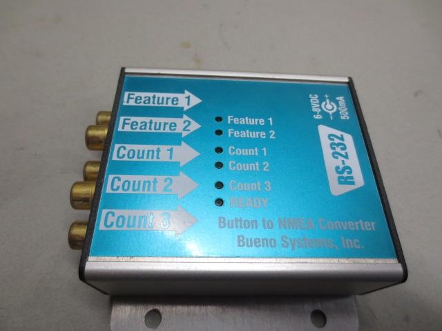
The unit has performed flawlessly over the course of 15+ years. But now, my friend wanted a spare, you know, just in case ... Well, the SX chip I used is obsolete, so I had to start again from scratch. Here's a photo of the original unit:
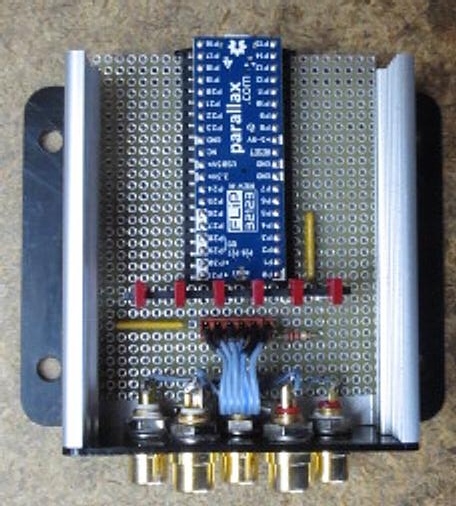
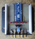
I designed a replacement using the Propeller FLiP module. This was much easier than the original, so much, in fact, that I decided not to do a custom PCB, opting for Vectorboard and point-to-point wiring instead. I had only to add some LEDs, a couple of resistor networks, another resistor, and a header for the buttons. The FLiP module has everything else in a compact form factor. Here's a view of the interior before final assembly:
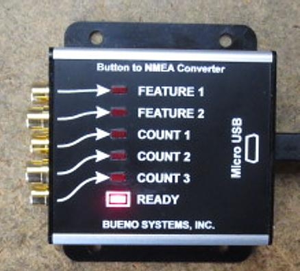
And one of the finished product:
I programmed an 87-line program in Spin that uses two cogs and locks to handle the buttons and transmit the data. I've always considered Spin to be a rapid-application-development (RAD) language, since it's so easy to cobble together elegant, working code in short order. (The original SX code was dozens of lines of SX ASM and took probably five times as much time to write.) Was the Propeller underutilized in this project? Yes. Does that matter? No!
The FLiP module is an OEM's dream. It's inexpensive and enables not only RAD, but rapid product development (RPD), whether the volume is one or hundreds. I cannot say enough good things about it. And I was able to build the spare device for my friend at much less cost to him than the original.
-Phil
The original device I built for him used an SX processor, programmed in assembly, along with a voltage regulator, a logic-to-RS232 convertor, and numerous passive components, to accomplish the necessary functioning. I designed a PCB to accommodate all of those numerous parts and had it fabricated, after which I populated it with the SMD parts that it required.
The unit has performed flawlessly over the course of 15+ years. But now, my friend wanted a spare, you know, just in case ... Well, the SX chip I used is obsolete, so I had to start again from scratch. Here's a photo of the original unit:

I designed a replacement using the Propeller FLiP module. This was much easier than the original, so much, in fact, that I decided not to do a custom PCB, opting for Vectorboard and point-to-point wiring instead. I had only to add some LEDs, a couple of resistor networks, another resistor, and a header for the buttons. The FLiP module has everything else in a compact form factor. Here's a view of the interior before final assembly:

And one of the finished product:

I programmed an 87-line program in Spin that uses two cogs and locks to handle the buttons and transmit the data. I've always considered Spin to be a rapid-application-development (RAD) language, since it's so easy to cobble together elegant, working code in short order. (The original SX code was dozens of lines of SX ASM and took probably five times as much time to write.) Was the Propeller underutilized in this project? Yes. Does that matter? No!
The FLiP module is an OEM's dream. It's inexpensive and enables not only RAD, but rapid product development (RPD), whether the volume is one or hundreds. I cannot say enough good things about it. And I was able to build the spare device for my friend at much less cost to him than the original.
-Phil



Comments
Totally agree. Utilisation doesn’t matter, and component cost quite often doesn’t either. Quite often it comes down to the design cost. Getting things done simply and easily.
The elegance of the prop using a mix of spin, and PASM where needed, make for fast solutions. Speed isn’t always a requirement, and that’s where spin shines. The ability to just drop in a PASM cog (core) when speed is required is a significant factor.
There’s nothing like the prop, and P2 significantly extends this.
Same extrusion as the earlier one?
Panel screen printed?
No: laser-engraved on Rowmark laminate.
When I built the first unit, I did not yet have a laser cutter. So the mounting plate was done in aluminum, and the endplates in black FR4, on my CNC mill. The panel legends were done using a UV lamp and film negative over 3M's Dynamark II sheet. It'd be nearly impossible to do that now, since commercial printers use digital direct-to-plate technology and have jettisoned their film printers.
The new unit uses laser-cut acetal copolymer in place of the aluminum and FR4. So everything gets fabbed with a lot fewer steps than before. I hardly ever have use for the CNC mill anymore. When I first bought the laser cutter, I had no idea what I was going to do with it; I just knew I wanted one. Now, I could not do business without it.
-Phil
I suspect a good proportion of phones and tablets are discarded merely because their micro USB connectors (mainly only used for charging) have broken.
That's a nice, rugged-looking unit! What is it used for?
At least on the FLiP, it's anchored via thru-holes and not just SMD soldered. And if something does break, the FLiP can be popped out of its socket and replaced for 30-some dollars.
-Phil
Same for marathon, and long range live broadcast transmission.
We use one small 400Mhz frequency to embed position of many moving items.
6 motorbikes, 2 helicopters, one plane and a ground station need for a common race.
The frequency of transmission is from 2-7Ghz, we need the rx and tx parabolic antennas to point to each other.
The plane is the place where all cameras signals go, are multiplexed in one stream, and send back to the stationary broadcast truck at the finish
The antenna motors are ingenious swiss made fast speed multisteps mounted on the wings
The unique 400Mhz frequency is divided to 1/3 sec transmission spaces.
The interval for transmitting the position and height, depend on speed of the object
The GPS pps is used to define the right space to transmit.
Every object has his unique ID, time space and repeat rate.
If one of the units go wrong on transmit, the whole system is jammed.
The packets are hex encoded radian values, calculated from the nmea gps, all inside the same flip.
Connection in rs232 to the radio.
The pcb is for flip to rs232 ic, power management and breakout
=>
And of course I use a propeller so ...
-I have a cog over for display and human interface
On a different 400MHz reception for all the cameras....
-I have time and cog over to manage the whole Tally (=red light on camera) reception
-I have time and cog over to manage extra serial commands to the onboard broadcast transmitter
It is fun, it is user friendly, and rock stable for already several years.
The flip is in use from the last year
That a seriously complex application!
I understand that to achieve "rx and tx parabolic antennas to point to each other" you are continuously calculating the directions of the antennas by 3D geometry based on updated gps positioning.
Fun too, being part of the cycle racing!
We try with Arduino, but the propeller was a big jump forward.
We gain 22ms in the time critical loop part of the system with propeller.
One cog was dedicated for the pps puls and timing
For the field user we gain in user friendly configuration, and easy monitoring of all the parameters.
The chalange of the system is to be confident before the race start that all the components wil working well.
We have an time frame of 15 min to tweak before the live, flight time are very expensive.
We can't get the plane back to adjust one parameter. Some time the landing zone is 200km away
We can't stop the race to reach an motorbike in the race. If he is out of the race, it is really hard to get back in
We can't get an extra rf operator in the helicopters for flight time issues
We can't test the whole system before everybody is in place, no plane no links, no helis no relay.
We use an other system on the cameras with propeller for all the broadcast onscreen datas
Speed, inclinations, wind, temperature, battery levels on repeat rate of 2xsec ... but it use the propeller mini and the video link.
I mount it onto dspth free pad matrix board the same as you do Phil except i prefer pin headers on mounting boards and low profile female headers on the module.
-Phil
-Phil
You can't really do that when the module has pins and the other thing is that pins bend or break whereas the low profile sockets aren't readily damaged. I've tried both ways with modules and i like the sockets the best.
Seeing that the flip module is designed to plug into breadboard then it is understandable that it has pins for that purpose.
Btw, my matrix boards may just use normal height pin headers since i have boxes of those but any design that needs to fit in a height restricted area i use the low profile ones. I will post a picture later to show you the difference.
This is just a tip seeing that you use modules and matrix board for packaged prototypes like i do. Once I've done the proto there's no reason these days considering the cost to not go and get pcbs done.
Of course, those require a little extra board space, unless the soldered pins can be placed inside the FLiP's footprint. I designed a product with the FLiP where this wasn't possible, but I was able to attain enclosure clearance anyway by mounting the FLiP to the bottom of the board with other SMD components underneath it. The through-hole components got mounted top-side.
-Phil
Use "Attach a File" at the bottom of the field when posting to the thread. The link will be a pic(file) on your computer.
Don't see it catching on in Europe with Antratek wanting $54 + 2-3 weeks delivery. Can get 3 of Cluso99's wonderful device for that and probably quicker.
https://www.digikey.com/product-detail/en/parallax-inc/32123/32123-ND/7221216
Antratek is nice, but never the right amount or module in stock. Special the new items
Module: $32 +
Edit: Didn't see the "if you order 2"...Yes, free shipping applies but who's gonna spend $65 when they might only be curious?