Pan and Tilt Servo Project
 iseries
Posts: 1,526
Here's a project to test your skills.
Items needed:
Now Parallax sells the MCP3002 chip but I don't like this item as well as the MCP3202 because it is only 10 bit where the MCP3202 is 12 bit which works well with this gimbal unit. If you used the small Joystick unit, (27800), that one uses the full range of the pots so that the output values from the A to D converter is from 0 to 1024. But on the gimbal unit it has a limited range and would only output 0 to 256. Using the MCP3202 I get a nice range of +/- 500 units.
From there you just need to scale the value from the gimbal to the servos which need a range of 450 to 2450. You don't really need the full range. The servo has a nice 180 degree range for this project. The servos also need 5 volts to operate as well as the gimbal and MCP3202. I used a 5 volt buck convert for this.
Here is a link to the MCP3000 library I wrote for reading the MCP3202 Analog to Digital chip. MCP3000 Library.
In addition I used Parallax servo library to drive the servos.
This is the source code to make it all work.
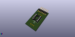
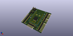
I made an adapter board that takes the Gimbal plug and interfaces it to the MCP3202 A to D board that then plugs into the Propeller board.
Here is a video to show it all put together using my Propeller Mini Plug and Play board.
Next I want to use an IMU to do head tracking.
Mike
Items needed:
- Propeller Mini (32150) to translate Joystick movement.
- WiFi Module (32420D) for loading code.
- Gimbal Joystick (27808) to move pan and tilt servos.
- 2 micro servos for pan and tilt.
- MCP3202 A to D converter chip to determine position of gimbal.
Now Parallax sells the MCP3002 chip but I don't like this item as well as the MCP3202 because it is only 10 bit where the MCP3202 is 12 bit which works well with this gimbal unit. If you used the small Joystick unit, (27800), that one uses the full range of the pots so that the output values from the A to D converter is from 0 to 1024. But on the gimbal unit it has a limited range and would only output 0 to 256. Using the MCP3202 I get a nice range of +/- 500 units.
From there you just need to scale the value from the gimbal to the servos which need a range of 450 to 2450. You don't really need the full range. The servo has a nice 180 degree range for this project. The servos also need 5 volts to operate as well as the gimbal and MCP3202. I used a 5 volt buck convert for this.
Here is a link to the MCP3000 library I wrote for reading the MCP3202 Analog to Digital chip. MCP3000 Library.
In addition I used Parallax servo library to drive the servos.
This is the source code to make it all work.
#include "servo.h"
#include "mcp3000.h"
#include "simpletools.h"

int scale(int);


#define PAN 16
#define TILT 0
#define CS 5
#define CLK 4
#define DOUT 3
#define DIN 2
#define REFV 5
int i;
int p, t;
int Pan[16];
int Tilt[16];
int P, T;


int main()
{
  mcp3000_open(CS, CLK, DOUT, DIN);

  servo_angle(PAN, 900);
  servo_angle(TILT, 900);
  pause(5000);

  P = 0;
  T = 0;
  for (i=0;i<16;i++)
  {
    Pan[i] = mcp3202_read(1);
    P = P + Pan[i];
    Tilt[i] = mcp3202_read(0);
    T = T + Tilt[i];
  }

  i = 0;
  while(1)
  {
    P = P - Pan[i];
    Pan[i] = mcp3202_read(1);
    P = P + Pan[i];
    T = T - Tilt[i];
    Tilt[i] = mcp3202_read(0);
    T = T + Tilt[i];
    p = 2880-scale(P/16); // reverse direction
    t = scale(T/16);
    i++;
    i = i & 0x0f;
    servo_set(PAN, p);
    servo_set(TILT, t);
//    printi("P:%d,T:%d\n", p, t);
    pause(1);
  }
}

int scale(int v)
{
  int i;

  i = 2000*(v - 1527)/(2530-1527)+450;

  return i;
}
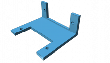
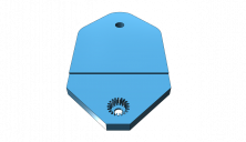
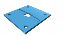
I also 3D printed the servo base, bracket, and camera mount which took no time at all to design and print.I made an adapter board that takes the Gimbal plug and interfaces it to the MCP3202 A to D board that then plugs into the Propeller board.
Here is a video to show it all put together using my Propeller Mini Plug and Play board.
Next I want to use an IMU to do head tracking.
Mike


Comments