Shifting registers
in Propeller 1
I'm trying to understand the register shifting used in counter examples.

What is the
If I wanted to designate PIN 5 as APIN, and PIN 12 as BPIN, what would the shift command look like?
Side note. I wish the preview for this discussion would work so that knew how it will look before submitting.

''Demonstration of NCO counter mode (%00100)
CON
 _clkmode = xtal1 + pll16x
 _xinfreq = 5_000_000
PUB NCO_single_ended_mode
' mode PLL BPIN APIN
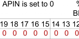
 ctra := %00100_000 << 23 + 1 << 9 + 0 'Establish mode and APIN (BPIN is ignored)
 frqa := $8000_0000 'Set FRQA so PHSA[31] toggles every clock
 dira[0] := 1 'Set APIN to output
 repeat 'infinite loop, so counter continues to run
What is the
about? If there is any more sifting of the registrar then the CTRMODE would not line up.<< 9 + 0
If I wanted to designate PIN 5 as APIN, and PIN 12 as BPIN, what would the shift command look like?
Side note. I wish the preview for this discussion would work so that knew how it will look before submitting.


Comments
If someone could point to some reading material I would much appreciate it.
Thanks.
https://www.parallax.com/sites/default/files/downloads/AN001-P8X32ACounters-v2.0.pdf
https://www.parallax.com/product/32305
There are 3 components being combined together,
%00100_000 << 23 ' counter mode and plldiv
1 << 9 ' Bpin is 1
0 ' Apin is 0
+ is being used to combine them (ORing is more normal, but the effect is the same as the
bitfields do not overlap so no carrying can happen).
If I wanted to designate PIN 5 (on the Propeller chip) as APIN, and PIN 12 (on the Propeller chip) as BPIN, what would the shift command look like?
CON
    Apin = 5
    Bpin = 12

...
...

    ctra := %00100_000 << 23 + Bpin << 9 +Apin