Omron power supply dies in 5 minutes
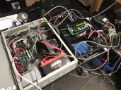
I normally use unregulated 27V off the bridge rectifier for DC power to my BLDC motors. But I have a case where I want to drive two motors under a heavy load and I know it would stress my power supply. The blue transformer is rated at 2.6 amps (1.3 + 1.3). 6 amp bridge rectifier. Never blown one up even when I have measured 6 amps load for a few minutes of operation. So I looked at McMaster and they had a 10A din mount supply. $220. I felt like this would be overkill for the purpose. I put up two motors on the table, no load. I was putting some load by grabbing the output of the gearbox with some pliers about 3-4 times to see the current via ADC output on the LCD. No where near the load the motors will really have on it in the real world. Next thing I know the motors stop. Omron LED is off. Powered off and on. Nothing. Hour later. Nothing. What the heck. The Omron is the large black module in the gray box. S8VK-G24024. I put in a back plane and mounted the omron on the plane with an aluminum bracket. I added thermal grease on both surfaces to move some heat off the box.
https://www.ia.omron.com/product/item/5307/
https://www.ia.omron.com/product/item/5307/


Comments
The idea is doable as a whole. You should put a large capacitor on the regulated supply wires too. This allows small amounts of regen to be captured without the Omron freaking out from over-voltage.
You'll have to be careful of heat build-up in the enclosure but it shouldn't be more than the linear produced so I'm thinking that'll be okay.
Can I combine several of my standard xformer>bridge rectifier>cap supplies. Or is it better to connect one of these to one motor and one to the other. What about connect the outputs of 3 of my standard supplies. For a 2.6 x3 rated output based on the xformer rating. These supplies never break.
In the smaller black box there is the blue xformer>BR that gives 27VDC. It powers a switching 5v and switching 15v reg. Very low current draw. In the gray box I can fit 1 of the standard Power supply PCBs laying flat. Or 2 on edge. What if I combine outputs from 3 of these xformer>BR supplies.
Yes, matched transformers share well. Don't even need dual bridge. I recommend using Schottky diodes. How many motors?
Regarding the Omron again, you're probably okay to have all motors on the one supply. Just add some capacitors. If there is one motor, like a spindle, that has large regen, then it may be best on its own.
Drives that are built with AC supply connection will also have their own regen dump circuit. The internal dump will heat the drive's main heatsink. There will also usually be a pair of terminals for attaching an external dump resistor.
Drives that only have DC supply connection often leave that job to the external supply since the supply is also the drive's DC bus. Problem is an ordinary power supply has no concept of regen, therefore has no dump circuit. Adding a set of large capacitors on the DC supply is usually enough for light-weight point-to-point motion control. Pick'n'place is good example.
This is the plain coil version. Same specs.
https://www.digikey.com/products/en/transformers/power-transformers/164?k=Amveco+transformer&k=&pkeyword=Amveco+transformer&sv=0&pv1120=1293&pv1120=1487&sf=1&FV=ffe000a4&quantity=&ColumnSort=0&page=1&stock=1&pageSize=25
https://www.mpja.com/24V-10A-Center-Tapped-12-0-12-Transformer/productinfo/27846+TR/
Or
https://skycraftsurplus.com/24-vct-transformer-10-amp-120220-vac-12-0-12-120240v-rp8153.html