P2bot
in Propeller 2
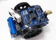
I wanted to have a P2 robot before the end of the year! Made it by 22 minutes. Happy new year everybody!


Comments
Mike
I've been trying to get mine to work but they just won't do anything!
I have them connected to the 5V on the P2-ES. Would that provide enough power? It worked on the Arduino so I don't see why it would not here.
I have both a standard continuous servo and a mini 180 deg. servo just like your robot setup.
Thanks!
J
5V out on that P2-ES board comes from the USB power, so all you need to do is make sure your USB supply is beefy enough.
I think you might need to connect a power supply (or USB battery power bank thingy) to the left-side "P2-USB" input, as that will handle up to 2A.
In comparison, the right-hand side "PC-USB" socket is limited to around 500mA, which might not be enough to keep all your servos running.
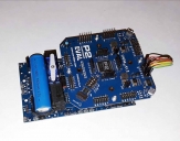
This was just a quick hookup to see if I could get a P2 robot doing ANYTHING before the end of 2018. ( I didn't want to watch any more of the marathon British interior decorating show my wife was watching for our exciting new year evening) The base robot is one I designed for the Arduino. The P2 is just sending "Left, Right, forward" signals to the Arduino that's actually running everything. No real intelligence in the setup.
I didn't want to blow a $150 P2-EV board doing something that a $2.65 Arduino can do just fine. I'm not going to be hooking up anything that pulls enough power that it might pop a trace, blow the power supply or God forbid, kill the P2. Once chips are readily available and the development packages get a bit more fleshed out, it will be time to integrate everything into a P2.
If you're going to be running a robot with the P2-EV board, I suggest you use external power ( battery or otherwise) and not try to pull power from the P2.
I've been working on an industrial board for the P2 but I've got that layout mostly done now. I may start laying out a robot board soon. That one will have plenty of current capability.
Yes, Bob, I'm looking forward to seeing what all these crazy geniuses can do with the P2 as well. That Goertzel stuff feels more like black magic than engineering. I'm hoping just to be able to UNDERSTAND it someday, let alone actually designing something around it.
This is, as far as I know, the first robot made with the P2. We need to see that thing perform now to really award the certificate of achievement. What's it going to take? A TAQOZ program, a bit of PASM?
Looking forward to it!
Ken Gracey
This means the "first P2 robot" title remains unclaimed!
Ken Gracey
There are no P2 chips available to build anything right now.
The robot was last used in 2004 at the Eastern Canada Robot Games, named it Extinguisher.
Back then it used 3 PIC16F877, 1 each for motor control, sensors, master controller.
So far I just have the P2 connected to the LMD18200 motor drivers and running open loop.
The motors have quadrature encoders that I'll work on connecting when I get a chance later in the week or next weekend.
After that I can work on interfacing the SRF04 rangers and possibly test the UVTrons and IR sensors that were used for flame sensing.
Current program is just running through sequence of PWM values using TAQOZ.
C.W.
Anybody else second the motion?
Ken Gracey
Ken Gracey
Integrating TAQOZ into the ROM seems to be a good decision. I by myself have still a hard time with FORTH but everybody here who has a P2 EVAL is now dipping his feet into TAQOZ, just for first tests.
And @"Peter Jakacki" is praying this since years, that interactive development in FORTH allows to do a fast simple function test of attached hardware without the whole write/save/compile/upload/run/say !$#^% cycle.
well done,
Mike
It was fun to start putting some "life" back in the old robot.
TAQOZ is definitely going to be a big plus, as well as the monitor.
C.W.
It would make a great "from scratch" example of using TAQOZ for robots :-)
J
Not much to see yet, so far just a quick test to make sure the drives work:
LMD18200 connections
RH motor: P0 PWM, P2 Dir, P4 Brake
LH motor: P8 PWM, P10 Dir, P12 Brake
C.W.
I'm currently converting my 6 axis (P1) cnc code over to my Eval board. I'll be sure to post a video of one of my machines moving when I get it working. I managed to get it to compile yesterday but I don't know enough about how to pass data back and forth between cogs yet to be able to send it a series of movement commands.
I used Forth to program some of my first cnc machines many years ago. It always amazed me that I could sit down and write a full pick and place robot routine in just a few lines of code. I never understood why it wasn't more common with control programmers. ( I had to go to C++ for compatibility reasons) It's nice to see it alive and well.
I did some of the "Blink" functions as the first tests of my P2-EV board of course, but not being able to go past command line input ( as far as I know) yet is a bit of a limit on how complex I wanted get with it.
Do you have a way to write your forth code to a file then download it to the P2? There is so much to learn that it's probably out here somewhere in the ever growing list of posts but I haven't been able to find it yet. I've been focusing on learning the P2's assembly instructions.
I managed to load my CNC code onto the EV board. yesterday. I know it's running because I embedded some diagnostics in the code to flash the onboard LED's at different points. I've got a small 5 axis machine sitting out in one of my sheds. I was running it with a P1 but it will make a great testbed for the P2 if it's still functional... ( it's sorta halfway exposed to the weather.I don't know if the drives are still good. )
If there is a way to write a TAQOZ program and put it on the SD that would be great. I look forward to being able to combine my (asm) movement function with higher level code on the P2.
I found that I couldn't do a serial download once my SD card was in place. It would be really handy if there was some sort of "Pass-through" function that would let us send a program to the SD card through the EV board while it's connected to the USB port. I suspect one of these smart guys out here will have something like it working soon.
I know the P2 is going to be a wonderful control-centric chip. I look forward to seeing more of what you've done with it.
KenB
For the sake of discussion, I think there are some simplifications that can be made to your code.
Each of your words has a BEGIN but does not have a matching UNTIL or AGAIN word. Remove the BEGIN from your words and then only use the BEGIN AGAIN loop words in your "main" line (last line of your example).
For your RSTOP and LSTOP words you can turn off the Smart Pin PWM with the MUTE word.
Give this a try instead:
j
I was "cargo cult'ing" off of some of the example word definitions and I see now that they only started with BEGIN because they actually had a loop, I was thinking all word definitions started with BEGIN.
I also see MUTE now, so that will be a good change.
I'm not sure yet how much TAQOZ will be used for long term code on the robot, but it is great for hardware testing.
C.W.