Industrial P2 Board
in Propeller 2
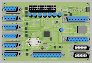
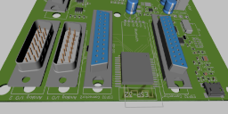
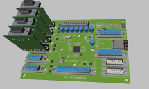
These photos are a rough layout of a P2 board I'm working on. I do mostly machine and motion control so the design is aimed at CNC, 3D printers, etc. However, the flexibility of the P2 allows signals that once would have been only digital or analog to be changed on the fly so any application needing lots of I/O and solid connectors might be a good fit.
I realized that a lot of board space was going to be taken up with power supply components if I used a single voltage input so given the cost of ATX power supplies ( ~$30) and the fact that most of us have one or two sitting around on the shelf somewhere, I elected to use the ATX power supply for power.
There are over 140 I/Os of various kinds brought out on this board. Most boards would never be built with all of the components installed but I wanted a flexible “Base” design that can easily be configured for a wide variety of applications.
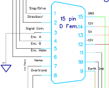
The 15 pin connectors have 5 P2 pins, 4 serial expansion port pins, Ground, +12, -12, and 5V.
The P2 pins are for things that need to be fast like step and encoder signals or analog like drive and feedback. The digital expander pins are for “slower” things like limit switches and operator input.
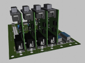
Six rugged connectors and multiple voltages allow for mounting small add on boards like the stepper drives shown in the attached photo. These same connectors would be great for most of the sensor and control modules available for the Arduino as well.
Mounting holes for a 40mm fan and power ports for the fan and (P2 controlled) thermoelectric cooler will let over-clockers keep the P2 Cool.
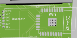
Mounting for either a cheap Bluetooth module or an ESP32 provide wireless connectivity.
Mounting for prop plug components or USB for programming.
I/O's:
57 P2 port pins (analog and digital)
48 Serial expanded 5V Pins
37 ESP32 Port Pins ( some analog some digital )
Battery Backed Up Real time clock
Low Power Bluetooth / or ESP32 Wifi-Bluetooth
Usb or prop plug programming
SD Card
Connectors:
1 - ATX power connector: Ground, 3.3V, +12V, -12V, +5V, Power Enable.
6 - 15pin female subD connectors: motion control/sensor / General purpose ports.
2 -15 pin male subD connectors: optomized for analog signals.
1 - 37 pin Auxillary I/O port with 24 port expanded I/O's, 8 P2 port pins, +3.3V, +5V, +12V, -12V, and Ground.
This board is still a work in progress. I've been working on it for my own needs, but if I get enough interest I will consider selling bare/partially/fully stuffed boards. Any suggestions about what I've missed, what doesn't/does make sense, what you like, don't like etc. will be considered for the next iteration of the design. I'm not including the schematic here but will later if I get enough interest from the group. I have absolutely no idea of costs at this time, but will do my best to keep it down to a dull roar.
Feedback appreciated.




Comments
Nothing wrong with D connectors, they can be used easily for board-to-board, -cable or -idc. Are your tracks clear enough of the jackscrew holes? (ie clear of the washers/nuts used with jackscrews)
Also how would a fan connect? Couldn't see a header
RTC is a nice touch. Great to see a decent industrial design
cheers
Lachlan
I like to keep the Flash and SD really close so the speed is not limited by track length and termination (and noise).
Something I find useful in an industrial/commercial design is to make it a point not to have a battery. Besides being bulky, they will at one point require replacing which means powering off, and opening it up which may lead to possible damage. At that time they will have to reset the clock as well.
Why not use a small supercap instead of a bulky battery plus these caps don't leak or explode.
I use tiny 0.1F caps or smaller and find that they power the RTC for up to a week. The crystals I use are about 0805 size though but I find the I2C DS3231 style RTCs easier to use and more accurate.
If an industrial unit has not been in use that long then usually it's because it is out of action anyway and you simply reset the clock as you would when the battery fails.
Cheers
Peter
The photos are shots of my first swipe at a layout. I've added a few things since that picture: servo connectors, high current transistors for the fan and thermoelectric chiller as well as the connectors you mentioned. (Good catch!)
I've started on the routing but I have quite a ways to go. ( the Diptrace autorouter leaves a lot to be desired.) I appreciate the mention about the mounting and fan holes. I've done several P1 boards but this is my first P2 layout. Any "Gotchas" mentioned are appreciated. I'll give the holes as much clearance as possible.
There's enough stuff on the board that I'm having to do a manual layout. I wanted to see if anyone had any requests or suggestions before locking the design down but it's starting to "Firm up".
I like the D connectors also. I've found that the most expensive components on many boards now-days ARE the connectors instead of the chips. High quality connectors are often 10 - 30 dollars each but the Ds' can be found for under a dollar.
When I was laying out the 15 pin connectors for the motor drives I realized that the P2 is offering us something that no other chip to date has: The chance to define a new standard connection bus. The dual nature of the port pins being both digital and analog open up the possibility ( and the need) to define some new standards for add on modules. I've already done the simple unipolar stepper drive shown here. ( with Pwm level control it SHOULD be able to micro-step as well. ) These modules could be anything from simple relays to multi-channel digital scopes. Any suggestions about a standardized port for sensors, control etc. are welcome.
I'm hoping to have a minimum component P2 board that has open places on it for many of things people might want to add. I've been laying out the design with parts that I have been able to solder manually myself. 603 sm parts are the smallest I've been able to work with consistently. I may re-do the design later with smaller parts that are machine placed to leave more room for manual add ons. I'll post more shots as things solidify if anyone is interested.
This is GREAT news....you have a customer here.
The P2 is a control engineer's dream so we need an industrial package.
Have you provided +/- 10v analog command signals for conventional industrial servo drives?
Watchdog/dead man relay?
Not sure I agree with the 1-week battery (cap). Some countries shut down for the entire month of August.
You're right about the 2013 design Peter. I started that design when the P2 (hot) seemed imminent. This is the board I've been waiting to build for ... oh... quite a while now. I suspect you were pretty happy to be able to have real silicon to design for as well. Your P2D2 is a wonderful design and much appreciated by the community! You are light years ahead of me in your knowledge of the chip and it's code so I definitely appreciate your input.
Those "Isolators" you mentioned are at the moment only ferrite beads to keep spikes to the P2 to a minimum. For applications that need the absolute maximum of speed from the P2, they can be replaced with 0 ohm resistor packs. Another possibility is a resistor/capacitor network. ( I might add another couple of pins) I don't know enough about line termination to be able to say whats best. Most isolators REALLY limit your speed so I figure they should be designed into add-on modules if necessary.
The pictures shown aren't quite "Fake News" but like I said, they are a work in progress. One of the biggest issues IS the power traces. I'm trying to lay them out so that when I fry one ( which I know I will...), it can easily be repaired. It's that or having fuses everywhere. Every board is a bunch of compromises. I do product development and work with many different odd-ball applications. This board isn't really intended to be the final embedded design, it's mainly intended to be a convenient way of bringing out the P2's signals for prototyping that a "Final" design can be taken from. This way, most of the prototyping is just designing small plug in modules that do whatever needs to be done.
Some of what I was thinking about for a "Standard" to design around is stuff like the add on modules having standard sizes, current limits, fuses, signal conditioning, etc. to prevent damage to the main board. I won't really know what the power limits are until the final lay-out, but it's a good idea to be keeping these things in mind in the process.
You mentioned the +- 10 volts for servo drives Mickster. That's the reason I brought the +- 12 volts to the 15 pin connector. A small, add-on module with some op-amps should be easy to design and just plug into the same port that the steppers are driven from. As for power, I'm running power traces as large as possible to the connectors but traces can only carry so much power.
With an ATX power supply handy, there will be other (PC) power connectors available that can be designed into the modules and supply higher current. There's no sense in trying to carry 10 amps on the traces if the power is readily available and easily connected elsewhere.
Same thing for any other higher current add on modules, design them with the mounting for power connectors. If cost is an issue, leave the connector off and solder the wires directly (or use cheap automotive style crimp connectors) .
With well designed add-on modules, there's no reason they would need to be limited to the P2. A "Shield" adapter for the Arduino, Beaglebone, etc might open up some markets.
"We need Mack Trucks, not Ferraris"
(Dick Morley "father of the PLC")
Unpluggable....No chewed-up terminal screws to contend with and they accommodate real field wiring.
I tried to find them in a US distributor to check the prices but didn't find anything at Mouser or Digikey. Do you know a distributor I can check for stock and pricing? (doing the whole quote-request, 1 week delay, 12 week lead time thing doesn't doesn't play well with my ADDH thing)
An industrial board DOES need great connectors and if the SubD version of this board gets any traction I will probably up the game with more expensive connectors but I was trying to get the "Best bang-per-buck" on the first go round.
I think these would make great connectors for the add on modules! The Modules would be screwed onto the main board but for customers needing to plug and un-plug things, this would be great.
It'll vary a lot as to how helpful they individually are. Some have regular systems builders they supply to or even have their own assembly facilities. These wholesalers will be a lot better with both stock and catalogues to read.
For online ordering, however, I personally use RS Components for most parts of this ilk. Eg: https://nz.rs-online.com/web/c/connectors/pcb-connectors/pcb-terminal-blocks/
That would take some serious study to determine the best option for a given circumstance, but I see some high amperage ratings, so I am sure they would be worth a good study.
However, for the sake of discussion, and as it applies to my present project, where I have at least 10 wires that must enter a NEMA 1 enclosure, being (8) wires from two bipolar stepper motors and (2) for my laser, is there something available in that series that would screw mount to 16, 14 or 12 gauge steel, so that the steppers or lasers could easily be interchanged?
Getting back to your design. Keep it simple, and flexible, and follow the Parallax philosophy that sensors / peripherals will constantly change. So tying to accommodate every / lots of different sensors / absolutely has to have an "Ah Ha" moment with engineers and designers... We love the P2, but what about the other potential users out there?
These are always easy to work with once a suitable hole exists - https://nz.rs-online.com/web/p/heavy-duty-power-connectors/1138682/
No crimping or soldering.
EDIT: Oops, corrected the link for crimpless version. It gets really confusing trying to work out what fits what in those ranges. Definitely should ask for help from the rep.
https://www.mouser.com/productdetail/phoenix-contact/1881367?qs=F79NelsxgYF1owdCQkGluw==
https://www.alliedelec.com/phoenix-contact-1881367/70054698/
Phoenix are everywhere, I only showed Hitaltech.co.uk because I had a shortcut.
@idbruce
http://www.harting-usa.com/products-markets/harting-usacom/hanr-industrial-connectors11265/
Don't panic when you see the prices, pretty sure there are knock-offs. You can combine power & signals with these things.
Pololu prices are better
Nice find Mickster
I am with you on that. I once did a whole machine with Molex.... Never again.
There is a special tool that pushes them right out, if you like Molex
I have used both the smaller and larger size Molex... They are acceptable for some situations, but in others, I would avoid using them again.
Love it!
Like these.
I've left room to be able to put a single stage 40x40 mm peltier cooler on the top and a two stage ( stacked ) 250 watt chiller on the bottom. (not shown)
This isn't the kind of thing that anyone would do for "Real" ( the 250 watt cooler pulls 30 amps ) ... but I have enough liquid coolers, heat sinks, fans and thermoelectric modules sitting around to be able to try it for grins. Any idea if it would be worth-while to sandwich a P2 between two chilling plates?
Is heat the limiting speed factor or something else? I know Chip has clocked the P2 up pretty high, what's the maximum ( Liquid Nitrogen... etc. ) that the P2 might be able to run up to? How much heat would it generate?
I think Chip nudged 400 MHz, I'd budget 520mA or around 2.6 watts for the core. That doesn't include heading I/O loading (if you're direct driving leds, relays etc)
In my opinion the heatsinks won't help nearly as much as a heat spreading power plane, and/or small fan to move the air.