Cool $20 Gift for the Guy who has Everything
 erco
Posts: 20,263
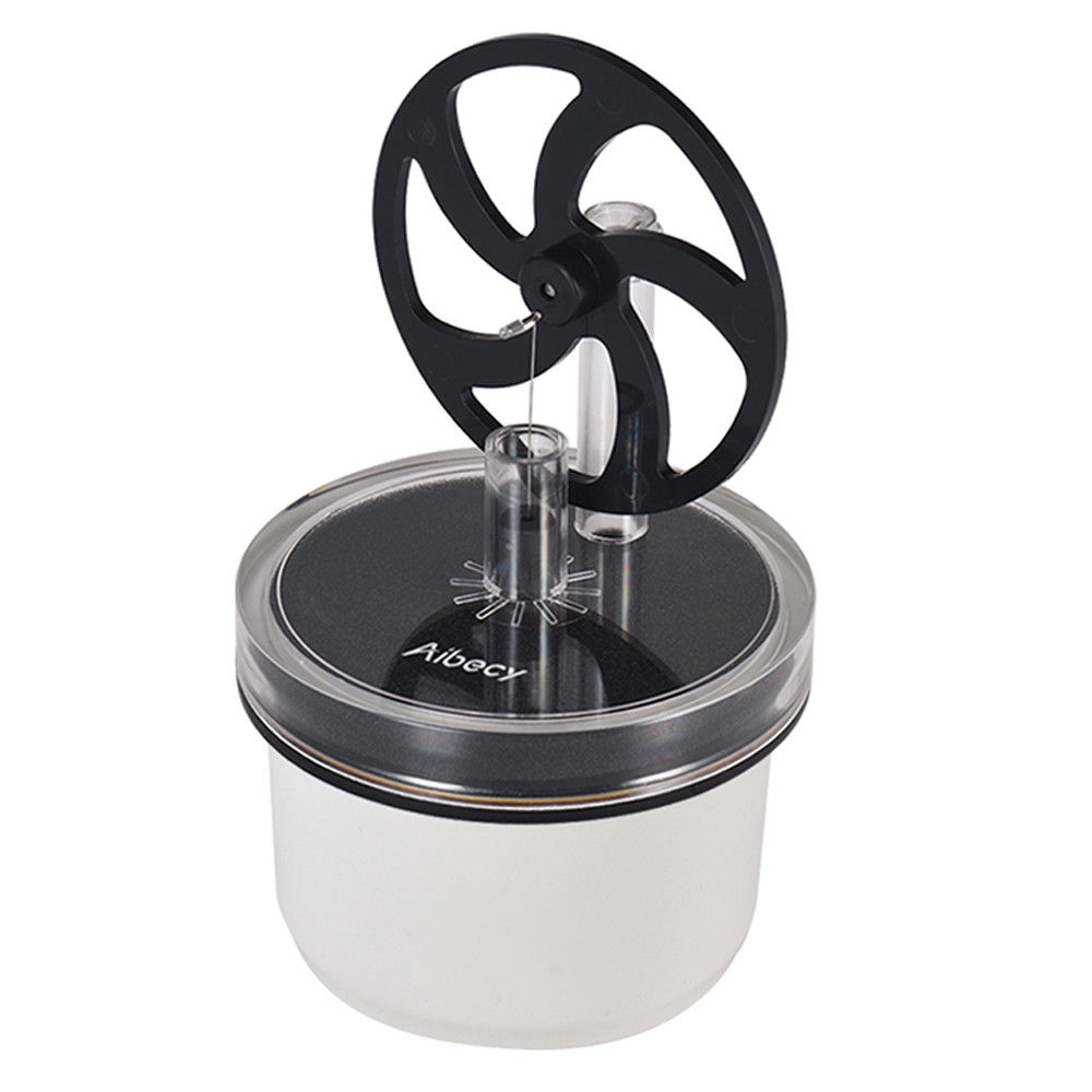
Sorry, not Parallax, not even electronics. But if you need a last minute gift, here's a $20 Sterling Cycle engine that runs off your mug of hot coffee. Seller is in Kentucky (most at this price are shipped from China) so there's a chance it will arrive before Christmas. I just ordered two, one for my brother and one to hoard.
ANYBODY WITH A COOL NEW COFFEE MUG needs one of these!
Maybe someone smart will add a magnet & coil and blink an LED... or power a Prop...!
https://www.ebay.com/itm/223215448837
Forum issue: recently when I "insert picture" I get 4-8 duplicates and must delete. Anyone else?

ANYBODY WITH A COOL NEW COFFEE MUG needs one of these!
Maybe someone smart will add a magnet & coil and blink an LED... or power a Prop...!
https://www.ebay.com/itm/223215448837
Forum issue: recently when I "insert picture" I get 4-8 duplicates and must delete. Anyone else?


Comments
How does that thing work? I don't see any connecting rod joining the flywheel to the displacer. It looks like the axle if fixed in the acrylic tower and the flywheel spins on a bearing but the only connection from the flywheel is to the power piston.
[img]https://goodgoods184_8.potmsg.com/i/w?u=/images/O/2/OS1232/OS1232-1-0d5f-pZKx.jpg[/img]
These cheap Stirling engines often only use a diaphragm for the power piston - gets around the cost of making a low friction, well sealed, piston and cylinder. You can make one yourself from a couple of old cans, a CD for the flywheel, a few bits of thin wire and balloon from which to cut the diaphragm. You can find lots of plans on the internet and in YouTube videos on how to do it.
In the first image you can clearly see the connecting rod (wire) attached a piston - unless it passes through the piston, if so what drives the flywheel?
There needs to be something driving the flywheel, and something 90 degrees out of phase driving the displacer. The axle going through the pedestal containing the main bearing is fixed, and is straight - I don't see how there could be any form of reciprocating motion driving it. The ones I have found use a crankshaft with two throws, one for the displacer and one for the power (diaphragm). Can you link to one that uses a single connection to the flywheel?
The Swedes use them in the latest generation of the submarines - the engines are very, very quiet.
But I must admit that I'm not sure how the manufacturer would be able to assemble something like that ( the tower would have to be in two pieces to allow the crank to be inserted, or the crankshaft would have to be built-up of several pieces? ) so I could be completely wrong. If the 'crank' for the power piston is just a gentle crescent-shaped curve, I suppose it could be slid in from one end.
I have seen YouTube videos of Stirling Engines that don't have any direct connection to the displacer - but they are usually in the form of a see-saw tube so that gravity can do the job of moving it as the tube tilts - and the one pictured in this thread can't work that way.
You can see that the flywheel is on a bearing - that means the shaft is stationary; so even if there were a crank inside the tower, it would not turn with the flywheel.
So I'm stumped. Maybe the whole thing is a scam and it doesn't actually work.
Edit: another idea. You could use the angle of the connecting rod (the angle from the vertical as it rocks side to side) to operate a sort of rocking lever mechanism inside the power piston - which would then cause the power piston to operate out of phase with the displacer. Seems a complicated and expensive way to do it though, and a two-throw-crank would likely be simpler, cheaper, and operate with less friction.
I have a low-temperature model Stirling engine that has roughly the same layout as the one shown in this thread, but it does have a two-throw crank and is much better engineered with ball races on all the rotating joints. It only needs a temperature difference of four degrees or so between the hot and cold ends to run, so it will run by just standing it on your hand, using body heat, or by placing it on a running computer or television or similar, or even just from sunlight shining on it.
I also built a small cheap engine from bits and pieces that ran - but it needed a much greater temperature difference. I used to stand it on top of a cup of boiling water which would just about make it run, or I could put it over a small flame or on a stove hot plate.
Different model, but here's a video of one working atop a coffee cup.
Right, in fact having the working fluid being in a closed system is essential. A tiny leak will render a Stirling cycle engine useless.
The large displacer piston alternates moving the working fluid (air in all the hobby level engines) from the cold side to the hot side and back with every revolution of the flywheel. The working fluid either expands or contracts depending upon which side it is on. This expansion or contraction of the working fluid either pushes or pulls the power piston, driving the flywheel. The displacer piston must also be connected to the flywheel* in order for the timing of the movement of the working fluid from one side to the other.
*There are a couple types of Stirling engine where the displacer piston is completely free, it either relies on resonance or pressure to move correctly. Neither seem to apply in this case.
I do suspect that the image does not show the actual engine, but I kind of hope that it is real...
If noone else ordered one, I will post my result here when mine comes
The shaft does not rotate, you can see a bearing on the shaft upon which the flywheel spins.
Even if that were not the case, how would a valve make it work?
https://www.walmart.com/ip/Aibecy-Low-Temperature-Stirling-Engine-Motor-Steam-Heat-Education-Model-Toy/882382245
I found another (different brand) with a power piston right in the middle, it had pictures of the piston taken out with a magnet in the end.
Being all plastic I doubt it will work as well as the ones with metal top and bottom plates. Plastic isn't exactly known for conducting heat well.
Here it is for $16.03 shipped: www.ebay.com/itm/Aibecy-Low-Temperature-Stirling-Engine
Makes sense to spin this motor via SPINning cogs.
And run a more traditional engine block using BLOCKLY.
http://507movements.com/about.html
The one I have, with a separate crank to drive the displacer, will only run in the one direction when you stand it over a cup of hot water. To get it to run the opposite way you have to make the top plate hotter than the bottom one - and one way to do that is to stand it on some ice cubes.
I suspect your engine won't run in either direction when stood on ice - the magnet displacer coupling only works for the hot end being the bottom plate.
It turns out this is a Stirling engine of the BETA configuration, and Wikipedia has a very nice diagram of how the various Stirling engines work.
The clever part about the toy is that rather than use mechanically complex crankshaft arrangements, etc to provide proper piston phasing, it uses the natural hysteresis of application/deapplication of a magnet to a metal disc to achieve this mechanical effect.
And rather than deal with the problems of a loose displacer piston in a necessarily large bore (cocking in the bore etc), it evidently is using a semi permeable foam disc which achieves the same thing.
This is all interesting to me because up until now I never knew what a Stirling engine really was, although I knew that they are supposed to be extremely efficient
For anyone interested in real world applications of stirling engines this video is worth watching.