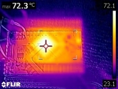
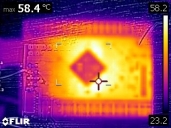
Thermal performance of Peter's P2D2 in 3 different orientations
 Tubular
Posts: 4,771
in Propeller 2
Some quick thermal pics of P2D2 with silicon loaded (glob top):-
1. Normal orientation with glob top of chip pointing upwards - see FLIR0496 - 72 degrees C
2. Upside down orientation with big ground plane pointing upwards - see FLIR0497 - 58 degrees C. The silver pad on the reverse side of the board doesn't play by the usual emissivity rules, hence the dark square, but this will actually be the hottest area.
3. (no cap) but side-on orientation had a peak temp around 70 C.
These test using the torture test suite running 8 cogs at 180 MHz. P2D2 was taking 280mA at 5V overall. The XCL220 reg hardly raising a sweat
Camera is a Flir C3. Its not designed for closeup circuit boards like the more expensive $3k flirs, but actually works fine. However the IR and visual cameras are about 20mm apart, and this causes an offset between the visual (edges) and IR (colours) in the combined image that it outputs, when you use it for close up work.


Comments
I was running at 340MHz last night with increased VDD. Seemed to be working.
Is this the spinning Fozzy torture test?
That was ntsc though, wasn't it? But only greyscale, wonder if the modulator IQ issue kills greyscale too?
340 MHz is amazing, Chip. And such a good low range on the PLL too. Certainly going to want a p2d2 overclockers edition, with 2 oz copper and programmable voltages like they do with PC CPU overclocking
Anyone up to posting some videos!?!
A comparison of P1, P2 @ 180MHz and P2 @ 340MHz would be stelar!!
Maybe it will be a new benchmark: Fozzie_spins/second :-)
@Tubular
YES !! Overclocking please :-)
340MHz opens up some exciting new opportunities for P2 !
j
You guys are clocking the silicon that high?
I had raised VDD to 2.0V. When we get the real packages, they will be able to convey heat away from the chip better.
There was a P1 job I did once using Phil's 'propstick', the main program had a long list of things to do a bit like a 'PLC scan'.
On that job, going from 6 MHz crystal to 6.25 MHz crystal kept the whole program in spin. Sure I could have gone to P1 PASM to gain speed, but its nice to have the option. With P2, we have many more PLL options to achieve the same
Actually I have a cat and 3 tame magpies that come to visit each morning for breakfast. They sing for it.
The birds aren't as patient as the cat, and the cat comes to tell me the birds have arrived, and asks "are you going to feed me or should i help myself to the magpies?". Then i get up, feed the cat dog food (so he eats slower), and feed the magpies dry cat food (which they like), and then we all get on with our day.
It's helped get me to work early during a busy few months, but unfortunately since work has slackened off a bit, the whole circus is tied to sunrise, and I'm looking forward to daylight saving starting this coming weekend, where all the above will happen at a respectable 6.30 rather than 5.30
If there is no color modulation, it should work fine.
I can see you asking OnSemi for a package with a top-thermal-pad too !!
There are quite a few overclocking and cooling offerings for the RaspPi & NanoPi
They range from finned heatsinks, to full fan assemblies.
This NanoPi Fan assembly example looks cute "Cooling Set + 3D housing, Irresistible Charm"
https://www.fabtolab.com/nano-pi-m3-cooling-set
or this
https://andahammer.com/index.php?route=product/product&product_id=242
http://www.nanopi.org/DUO-Heat.html
That last one is remarkably close to a nice fit on the P2D2 - just needs a squeeze to fit the 4 mounting holes.
Their heatsink uses 21.4 x 41.6 x 16 mounting holes on overall PCB 50 x 25.
I found more images here, this looks like another variant heatsink, thicker ?
https://forum.armbian.com/topic/7280-need-some-info-on-nanopi-duo/
They appear to use a thermal pad, which squashes to give some tolerance.
This is 2-D DXF PCB drawing, for the mounting holes (but sadly not the heatsink outline)
For more details refer to the document NanoPi_Duo_v1.0_1706 pcb file in dxf format
There is also a larger NanoPi NEO/NEO/NEO Plus2 Aluminum Heat Sink with Thermal paste and Screw pitch 35.4*35.4mm
more choices :
https://www.friendlyarm.com/index.php?route=product/search&search=heat+sink&description=true&sub_category=true
Anyone happen to have a Nanopi-duo they can measure the height of the package/heatsink clearance ?
If the clamping height is not P2 compatible, there are flat plane heatsinks too.
Seems I may need to scavenge a heat sink/fan combo from a PC motherboard (CPU) to use on an overclocked P2.
@lachlan, those 1500 chips might be in short supply as we burn thru them
Why stop there, the real over-clockers use cryogenic cooling !!
The peltiers are a little niche, whilst you can get all sorts of plumbing + Fins + Fans for cooling PC'c to below 1'C/W levels, from many sources.
There are videos of people out there, extreme cooling RaspPi etc, who are just a little nuts...
Another P2 avenue is under-clocking.
To power match an All-COGs-Full P1, the P2 needs to run circa 44MHz, which happens to also appx match ns/opcode
As voltage scales, the power scales faster & it seems 40MHz could run at greatly reduced Vcore ?
eg at 40MHz, the power curves predicted look like this :
Vcc=1.8 Pd = Cpd * Vcc^2 * Fi = 0.28512W
Vcc=1.2 Pd = Cpd * Vcc^2 * Fi Pd = 0.12672W
Vcc = 1.1 Pd = Cpd * Vcc^2 * Fi Pd = 0.10648W
ie Be interesting to see the the MHz/Vcc envelope, and how low can Core supply go, to still operate digitally/analog ?
The bottom of the chip is one big exposed thermal pad, just for that purpose. This package has a Tja of 20C/W.
Are you thinking about something like this?
thermonamic.com/TEC2-31-17-04-English.pdf
- The size of its cold side seems to be a good fit for the exposed metallic surface, at the bottom side of P2D2 or any other pcb;
- Its staggered construction would ease the placement of any smd components at the bottom layer, even at the near vicinity of P2;
- Due to its multistage construction, it's intended to be applied were great temperature differentials are expected to occur;
- Its overall thickness would keep any needed metallic heatsink away from pcb bottom layer, avoiding unnintended contact.
- Use preferably spring-loaded fixtures to secure the heatsink to the board, as to avoid any bending associated to thermal expansion differences between them.
Henrique
https://www.electrodragon.com/product/tec1-12706-thermoelectric-peltier-cooler-12v-60w/
and you can see the down side issues - this adds a lot of extra watts, (many more than P2) which need serious total cooling.
This comment too :
These devices must be used together with a heat sink to avoid burned in 2 seconds after powered up
Of course, if your target is to go below ambient, and not just close to ambient, then some form of active cooling will be needed.
If doing all this, some temperature sense would be needed, and a DAC for VCore control too ...
Maybe start with dry ice?
OC fun and games ahead. It's all fun, until someone torches a chip. Best wait for the production run.