Problem with DHB-10 and Arduino Shield
in Robotics
So I am building the Arlo robot.
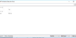
Today I was testing the connection between the Arduino and the DHB-10. Then as described in the assembly guide I got the wrong number inputs for fwver and hwver.
So I did the troubleshooting part from the guide but I don't know how to fix the problem now. In the attached picture you can see what's written in the serial terminal. But I don't know what Y1\r means or how to fix it. If someone could help me it would be awesome.


Comments
I'm not familiar with the Arduino setup, but does your Arduino have internal pull-up resistors activated ?
Are you able to add a line to your Arduino code that disables internal pull-ups on the pins being used for communication with DHB-10 and try again ?
Is that an Uno hiding under the BOE shield ?
In case no-one more expert chimes in beforehand, I'll set up a test jig on the weekend and see if I can figure out what's happening.
If you are getting the message no reply (timeout), that means the TX/RX pins were switched. I was trying to make the connection without the arduino shield, when I had the incorrect pin setup, I would get the timeout message.
I actually just purchased the Arduino BOE shield as well to make the connections, and I am still failing this test; however, you should try to run the following tests: Test-Motor-Connections and Arlo-Test-Encoder-Connections. I am actually getting the motors to spin correctly, as well as the correct encoder counts. I think this may be some firmware issue.
Yeah the uno is under the BOE shield
But where are the TX/RX pins? SO does your roboter work eventhough the dhb-10 connections is wrong but and the rest is fine?
Could the problems be with the motor wires because on one terminal the blue wire is left and on the other terminal the blue wire is right.
You've got them connected properly. The motors are bi-directional, so you only want to ensure you have the cables the same orientation on both sides - otherwise forward for motor 1 will be backward for motor 2
See this diagram that explains the pins. You're good with the motor wiring. Nice tidy connections and also nice short cables between the power board and your DHB-10.
In the meantime, I found an UNO board, and an old BOE shield. Today is manic in the office, but I'll pop in over the weekend to test them out. I don't have a MEGA board unfortunately, which @geistmate was using, but I figure the issue will be the same. Let's see if I can spot something with a fresh pair of eyes on the matter.
Set up the circuit according to: http://learn.parallax.com/tutorials/robot/arlo/arlo-arduino-uno-boe-shield-brain/connect-boe-shield-dhb-10
Run the test code to read fwver, etc... same problem as reported here.
Checked the voltage levels, and it seems ch12 is OK, but ch13 (rx at the UNO) might not be getting low enough.
It's off by about the value of an internal UNO 20K pullup resistor, so that could be one issue.
Also noticed an on-board LED on that pin 13. I'm thinking that swapping to using the UNO (via the BOE carrier) pins P10 and P11 (instead of P12 and P13) might solve. Out of time today, but will come back to this soon.
Maybe if I turn down the internal pullup resistor in the code? Maybe then it will work?
Did you ever solve your communication issue between your Arduino and the DHB-10?
By the way, I believe that it is pin 12, not pin 13, on the Arduino that receives the transmitted response from the Propeller through Channel 2 on the DHB-10.
Regards,
TCIII AVD
I'm now using this combination, Arduino UNO and BOE and I have the same issue. Could somebody solve this problema and can help me to solve it? I read some of the messages but I'm a little confuse.
I think that the solution is between pins 12 and 13 or 10 and 11 or disable some pullups but I'm not shure which is the correct and how I need to do that.
Thank you so much in advance.
Best Regards,
Pau
The communication issue is strictly a software timing issue and not a hardware issue.
I have gotten correct responses from the DHB-10 using the Arduino Uno R3 by sending an information request, delaying around 10ms, and then sending the request again. Works every time.
Checkout this thread for more information: forums.parallax.com/discussion/170266/problems-with-arduino-to-dhb-10-serial-connection#latest
Regards,
TCIII AVD