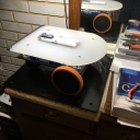
My new and improved Slammer II
Thanks to an inspiration from Whit, I have embarked on remaking my wooden bot, Slammer, into something aesthetically more pleasing and with increased versatility and functionality. Slammer II consists of two decks made of High Density Polypropylene, the power deck being black and the logic deck from a budget bread board from Bed, Bath, & Beyond. It is a creamy white translucent unit I picked up for around $13. This will be the home for my Parallax Flip module and all the things I can think of to make this a somewhat autonomous rover. Attached to the underside of this deck is the logic deck interface and a digital voltmeter that displays the battery voltage through the deck, behind the Flip module.
Most of my work so far has centered around the power deck, which holds two Turnigy 3 Amp Lipo batteries, buck Voltage regulator, the Parallax Bracket and Wheel Kit, power deck interface board, a dual LMD18200 motor driver, and a switch panel and charging station.
One of my goals was to make separating the two decks as easy as possible and I accomplished this by repurposing an old floppy drive cable which connects both decks together through a single cable. It's a 34 pin cable of which all the odd wires are ground and all the even wires are signal, which surrounds each signal wire with two ground wires.
I am currently using the motor quadrature encoders for providing speed control of each motor. On the power deck interface board I mounted a MC74HC86 quad xor gate to combine the A-B signals from each encoder into a single channel for each motor and sent that up to the logic deck. This particular chip is spec'd for 2-5 Volts Vcc, and runs just fine on 3.3 Volts. For the time being, I do not need the full quadrature capabilities but made arrangements to be able to switch over should I decide to do that.
I am going to try and attach a few pictures of this project and look forward to any suggestions or criticisms to help improve Slammer II.


Comments
Keep posting your updates, please!
So this 'bot is a descendant of the one you described in earlier postings that it earned its name because of colliding with walls? Yes? I remember it surfacing in a discussion regarding adding photos of stuff to a posting?