Shop OBEX P1 Docs P2 Docs Learn Events
Need Help with Square Waves — Parallax Forums

Need Help with Square Waves

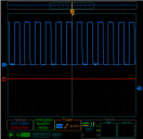
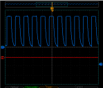
My goal is to generate a clean 38Khz square wave. I have a Parallax USB oscilloscope and as I increased the frequency the wave would no longer return to zero volts. I have screenshots at 250Hz, 2.22Khz and 6.57Khz. My question is can I solve the problem with a comparator or should I try to write this in PASM?
555 x 539 - 16K
551 x 472 - 12K
554 x 540 - 15K
«1

Comments

  • Peter JakackiPeter Jakacki Posts: 10,193
    edited 2018-07-30 00:48
    That's a problem with the scope of course, it must have very very limited bandwidth. Probably only designed for low audio frequencies.

    edit: just checked the specs but they only say "25Msps", so you may have a setting that lets you change the sample rate.
  • jmgjmg Posts: 15,172
    lardom wrote: »
    My goal is to generate a clean 38Khz square wave.

    You have not said how you generate your square wave ?
    Those scope traces look strange, as the rise time is much faster than the fall time. - rather like a Open-drain-P-FET would produce.
    Do you have a CMOS (push pull) configured output ?

  • Peter JakackiPeter Jakacki Posts: 10,193
    edited 2018-07-30 01:53
    jmg wrote: »
    lardom wrote: »
    My goal is to generate a clean 38Khz square wave.

    You have not said how you generate your square wave ?
    Those scope traces look strange, as the rise time is much faster than the fall time. - rather like a Open-drain-P-FET would produce.
    Do you have a CMOS (push pull) configured output ?

    Yes, agreed. I just had a close look at it now and there is that strange output as if it were source drive with a large pull-down resistor.

    @lardom - what's the output from the Prop pin itself? Are you using a counter or doing this in software. Either way, you should always post the software that you are using.
  • You can use a counter go generate a 38kHz square wave. Easy-peasy, no PASM required.
    pub freq_out(ctrx, px, fx)
    
    '' Sets ctrx to frequency fx on pin px (NCO/SE mode)
    '' -- fx in 0.1Hz units (100_0 = 100Hz)
    '' -- use fx of 0 to stop counter that is running
    
      if (fx > 0)                             
        fx := ($8000_0000 / (clkfreq * 10 / fx)) << 1               ' convert freq for NCO mode    
        case ctrx                                                    
          0, "a", "A":                                               
            ctra := (%00100 << 26) | px                             ' configure ctra for NCO on pin
            frqa := fx                                              ' set frequency
            dira[px] := 1                                           ' make pin an output
                                                                     
          1, "b", "B":                                               
            ctrb := (%00100 << 26) | px                              
            frqb := fx                                               
            dira[px] := 1                                            
                                                                     
      else                                                           
        case ctrx                                                    
          0, "a", "A":                                               
            ctra := 0                                               ' disable counter
            outa[px] := 0                                           ' clear pin/driver 
            dira[px] := 0                                            
         
          1, "b", "B":                         
            ctrb := 0 
            outa[px] := 0  
            dira[px] := 0  
    

  • You could use a AD9850 DDS module with the prop. Cost about $10-$12 eBay , Amazon etc.
  • DigitalBob wrote: »
    You could use a AD9850 DDS module with the prop. Cost about $10-$12 eBay , Amazon etc.

    Really? For a 38kHz square wave that the Prop can generate in software from any of 8 cogs or in hardware from any of 16 counters?
  • I use it for all of my function generator projects. I use the prop too straight up I'll post the spin file I might of used a JonnyMac spin file for that I don't remember.
  • jmgjmg Posts: 15,172
    edited 2018-07-30 03:40
    DigitalBob wrote: »
    I use it for all of my function generator projects. I use the prop too straight up I'll post the spin file I might of used a JonnyMac spin file for that I don't remember.

    AD9850 is good/great if you need Sine waves, but the OP asked for square waves, so the NCO mode of the Prop counters should be fine.

    Precision of the Counter hardware is ~ 20 millihertz according to AN001.

    If the OP is lucky enough to have a 5000001.14111MHz crystal, they will get exactly 38.0000kHz NCO.
    ie the point is, the numeric precision, is better than generic crystal tolerance, by far.
  • Yet the IR bandpass filter is purely analog and does not have the benefit that the Prop's crystal affords.

    @DigitalBob - I protested because you came in with a much more complicated solution when the op is struggling just to do a simple square wave. If we want to be of real help, we should keep it simple. Now if the op needed a very wide range of sine waves etc then DDS is one way to go. But no, anything close to 38kHz will do and the counters are a very simple solution. In fact you don't even have to do anything in particular in Tachyon, just type "26 APIN 38 KHZ" to make pin 26 use counter A set to 38kHz.
  • The code I used to generate 38Khz is adapted from what I normally use to drive DC motors differentially. I never looked at the signal through a scope but it has always worked without problems.
    I pass a value to a global variable which represents the duty cycle:
    PUB main(j)  'will alternate between 0 and 421
     
        broadcast := j    '421 should = about 20% duty cycle
    
    PUB Generate_Pwm | tc, t                      
      '38,004Khz
      ctra[30..26] := %00100                  'NCO single-ended
      ctra[5..0] := 1                         ' Set pins for counters to control             
      frqa := 1                               ' Add 1 to phs with each clock tick                          
      dira[1] := 1                            ' Set I/O pins to output 
      tC := 2105                              ' Set up cycle time   
      t := cnt                                ' Mark current time.
      
      repeat                                  ' Repeat PWM signal
        phsa := -broadcast                    ' Define and start the A pulse                         
        t += tC                               ' Calculate next cycle repeat
        waitcnt(t)
    
    The code I used to make the screenshots was simple.
    dira[1]~~
      repeat
        outa[1]~~                
        waitcnt(clkfreq/38000+cnt)
        outa[1]~                 
        waitcnt(clkfreq/38000+cnt)
    
    The first thing I did was connect an LED to the output of an IR receiver and test with a TV remote. That worked fine so I tested my code. The results were inconsistent. I tried to inspect the waveform through my scope and it looked like a 'saw blade'. That's when I decided to ask for help.
  • Peter JakackiPeter Jakacki Posts: 10,193
    edited 2018-07-30 13:31
    But where did you connect the probe? It looks like it is connected to a source driver (i.e. a PNP) with a passive pull-down since it takes time to pull-down the line due to stray capacitance. If the probe is on the Prop pin itself we expect to see clean edges but if that is not the case then something is wrong with your Prop or board.

    In regards to the "pwm" software, you are making it too complicated and the solution is way simpler. You only need to set the counter to nco to output a frequency of 38kHz and just leave it running. All the cog has to do then is modulate it and one of the ways of doing that is simply turn the DIR bit on or off.

    BTW, here is Tachyon enabling the counter for 38kHz and then I read the setting. The Prop is running at 96MHz.
    ...  15 APIN 38 KHZ  ok
    ...  CTRA COG@ .LONG 1000.000F ok
    

    You can also modulate it by driving the output high thereby overriding the pin and if it is connected to a PNP then it effectively turns it off. The other way is to directly disable and enable the counter through ctra.
  • It is not a problem with the PropScope. I have created and scoped faster waveforms than 38kHz with it. To this looks like there is some capacitance and a too weak drive to GND.
  • But where did you connect the probe?


    You can also modulate it by driving the output high thereby overriding the pin and if it is connected to a PNP then it effectively turns it off. The other way is to directly disable and enable the counter through ctra.
    For the screenshots I connected the probes directly to the Prop.
    "The other way is to directly disable and enable the counter through ctra."
    That sounds like a brilliant idea. JonnyMac's code disables the counter. I'm trying to figure out how to set it up. "How is the duty cycle configured?"

  • Peter JakackiPeter Jakacki Posts: 10,193
    edited 2018-07-30 14:33
    Just set it to NCO mode and write the value that corresponds to 38kHz to FRQA. It will generate a square wave, you don't have any control over duty cycle in this mode.

    Read AN001 about the Propeller counters.

    All you need to do is set the pin value plus the ctr mode into the correct fields. There's plenty of Spin code examples around but you should figure out how to do it yourself, then it becomes so much easier.

    edit: here is some Spin code to set the counter to a frequency (it seems to be much simpler in Tachyon :) )
    PUB Synth(CTR_AB, Pin, Freq) | s, d, ctr, frq
    
      Freq := Freq #> 0 <# 128_000_000     'limit frequency range
      
      if Freq < 500_000                    'if 0 to 499_999 Hz,
        ctr := constant(%00100 << 26)      '..set NCO mode
        s := 1                             '..shift = 1
      else                                 'if 500_000 to 128_000_000 Hz,
        ctr := constant(%00010 << 26)      '..set PLL mode
        d := >|((Freq - 1) / 1_000_000)    'determine PLLDIV
        s := 4 - d                         'determine shift
        ctr |= d << 23                     'set PLLDIV
        
      frq := fraction(Freq, CLKFREQ, s)    'Compute FRQA/FRQB value
      ctr |= Pin                           'set PINA to complete CTRA/CTRB value
    
      if CTR_AB == "A"
         CTRA := ctr                        'set CTRA
         FRQA := frq                        'set FRQA                   
         DIRA[Pin]~~                        'make pin output
         
      if CTR_AB == "B"
         CTRB := ctr                        'set CTRB
         FRQB := frq                        'set FRQB                   
         DIRA[Pin]~~                        'make pin output
    
    PRI fraction(a, b, shift) : f
    
      if shift > 0                         'if shift, pre-shift a or b left
        a <<= shift                        'to maintain significant bits while 
      if shift < 0                         'insuring proper result
        b <<= -shift
     
      repeat 32                            'perform long division of a/b
        f <<= 1
        if a => b
          a -= b
          f++           
        a <<= 1
    
    656 x 90 - 9K
    657 x 371 - 50K
  • lardomlardom Posts: 1,659
    edited 2018-07-30 16:42
    @Peter Jakacki, you were a tough tutor in 2007. You forced me to study but you guided me through my first Propeller project and when I was done I had a patent-able machine.
    2 to the 32nd power = 4,294,967,294. I'll need this to calculate FRQA. I'll use the PST to see what the code is doing, line by line. I'll get things working. Thanks.
  • I used the Chip G. Synthesizer. The AD950 module will give you square wave out of pin 7 on board.
  • Tracy AllenTracy Allen Posts: 6,663
    edited 2018-07-30 23:57
    Larry,

    The thread title specifically says square wave, but your question two posts back makes me wonder,
    I'm trying to figure out how to set it up. "How is the duty cycle configured?"
    Are the answers here addressing your real question? Also,
    The code I used to generate 38Khz is adapted from what I normally use to drive DC motors differentially.
    I pass a value to a global variable which represents the duty cycle:
    PUB main(j) 'will alternate between 0 and 421

    broadcast := j '421 should = about 20% duty cycle
    what exactly are you trying to do?

    The funky waveform--It is a separate puzzle. There is something wrong hardware wise with the waveform display, something wrong in the circuit or in the probe setup.
    For the screenshots I connected the probes directly to the Prop.
    If the probe is directly on the Prop pin, then I'd suspect that there is a diode or transistor that connects the Prop to a fat capacitor on the falling edge. Or, p1 is defective and has a high output impedance when sinking current. Try it on a different pin, not connected to anything outside.
  • @Tracy Allen, good call. I swapped the board.
    My plan is to build an IR joystick controller. If I can do it I'll post a video and the code.
    I also wanted to do something similar with 433Mhz modules but the signal is noisy and I'm not sure they're worth the effort. I'll experiment with a Schmitt trigger first, before I abandon the idea.
    @DigitalBob, I may take a look at the AD9850 DDS in the future. If I ever get around to experimenting with induction motors a variable frequency drive is something I think I'd like to work on.
  • I am surprized noone immediately came back and said "toggle OUTA, not DIRA", since
    the waveform is clearly due to switching from low impedance high output to high impedance
    floating (with the exponential sag due to 'scope probe resistance to ground).

    Any time you see a signal like this, or reflected version of it you can be sure the signal is
    being driven very asymmetrically, ie not by a push-pull output. Its a classic signature of
    a open-collector bus signal, for instance (well the reflected version of this).
  • Mark_T wrote: »
    "...floating (with the exponential sag due to 'scope probe resistance to ground).

    Any time you see a signal like this, or reflected version of it you can be sure the signal is
    being driven very asymmetrically, ie not by a push-pull output. Its a classic signature of
    a open-collector bus signal, for instance (well the reflected version of this).

    I have learned a ton of stuff in this thread. I appreciate everybody's input.
    After considering what Tracy Allen suggested I have a sneaking suspicion that I have caused similar damage to some of my other boards. Motors are inductive loads. I really think I should start using optocouplers in my designs.
  • Tracy AllenTracy Allen Posts: 6,663
    edited 2018-07-31 16:16
    Mark, Larry said that he was running the following test program to make the screen shots, toggling outa, not dira. Should be sharp up and down.
    dira[1]~~
      repeat
        outa[1]~~                
        waitcnt(clkfreq/38000+cnt)
        outa[1]~                 
        waitcnt(clkfreq/38000+cnt)
    
    Larry, why do you say,
    I'll experiment with a Schmitt trigger first, before I abandon the idea.
    Have you tried your test code on another pin? That will help determine if pin 1 is bad on that Prop, or if something else is going on with the circuit or the test probe setup.
  • lardom wrote: »
    2 to the 32nd power = 4,294,967,294.
    I'm nitpicking here, but the correct value is 4,294,967,296.
    Walter

  • Larry, if you are going to work with inductive loads you should really consider some study and experimentation with using R/C snubbers or back swing diodes to protect your drive electronics. Optocouplers will not prevent damage to your main drive circuits after the opto output. Example GE AMX 4 rotor/collimator driver circuit runs from output of opto through 2n3904/3906 totem pole drive stage to the gate of an IRF350. In this particular design which feeds a transformer for either driving a 24V lamp or a 110V anode rotation motor, the output of the FET is protected by a series connected resistor and capacitor (snubber) across the source drain connections. There are two of these stacked up between 110VDC and Gnd with the FETS driving the center tap of the transformer. The common form of failure when it happens is either or both FETs will get punched by a transient that the snubber can't quite handle. Replace them both, good to go. Worse case, FET completely shorted, 110 feeds back into the driver. lifts all parts and some traces from the board. But everything ahead of the opto survives. That's why Optos exist. Won't help the power drive circuit, only isolates it from the rest of the world. You may waste the power/drive circuit, but the rest should be protected up to the limit of the Opto's isolation voltage rating.

    I've mentioned in the forums in the past that many of the older medical imaging devices are heavy on motors, brakes, low and high voltage systems, video etc. The newer diagrams tend to be too blockish to be as helpful, but the 90s into the 2000s usually have some detailed schematics you can rob for working designs for various project ideas. The GE AMX4 (google ge biomedical selfserve) will bring up lots of products with usable schematics.
  • @Tracy Allen, I'm inclined to abandon the 433Mhz modules. They are cheap but noisy. I'll only go so far to get a usable signal out of them. I had success with the nRF24L01 modules which cost only slightly more. I'm still committed to a joystick IR controller.
    I swapped the board instead of testing other pins because it suddenly struck me that maybe you were on to something. It was possible that I damaged the board and I wanted to know right away if I caused the problem. I got a square wave with the second board. When I woke up this morning it occurred to me that I didn't say thank you. Thanks, please forgive my oversight. I will test the pins on the first board and post an update.
    Optocouplers will not prevent damage to your main drive circuits after the opto output.
    I hope your heath is improving.
    I'm thinking that I have to isolate my controller from my motors. With my nRF24L01 project I used Schmartboard PCB's. (I like the 2" x 2" form factor). Twice the receiver PCB's became unreliable. Finally, I replaced the receiver PCB with a through-hole board and didn't 'see' any more problems. I never had any problems with the transmitter board.
  • Peter JakackiPeter Jakacki Posts: 10,193
    edited 2018-08-01 01:01
    Larry, if you are driving motors and heavy loads then you most certainly should use double-sided plated through (DSPTH) pcbs. But they are of no use if you don't pay attention to the load ground and to the logic ground, which although both grounds, should have independent current paths, that is, the motor ground current should not flow through your control circuit, nor disrupt the ground level voltage. Safest way is to tie these together back at the entry point but there are many techniques, you just need to visualize currents and signals when you lay out a pcb. Even with optos you can still damage your circuit because of a poor ground but you could use isolated DC-DC converter modules to completely separate your grounds and power.
  • @Larry, Thx, moving along nicely considering. Just being grounded for 8 weeks kinda sucks. Anyway, MAX++ to what Peter is saying.
  • lardomlardom Posts: 1,659
    edited 2018-08-01 22:33
    @Tracy Allen, I did, in fact, damage that Propeller. I used that Prop for a project that had two DC motors and six servos. I tied up twelve pins. I will not make that mistake again. I swapped that Prop for a new one and the square waves were perfect.
    @Peter Jakacki, I have a project in mind that will require two Propellers on the receiving side. I am hoping I can use opto-isolators to allow both Propellers to read data from the same nRF24L01. I have been working on a robotic arm that has five DC motors. I connected potentiometers to the pivot points so I could control the position of the arm. It used up five cogs. I'll need another Prop for the wheels and pan/tilt for a camera. I want the controller to mirror the position of the arm.
    2029 x 1522 - 1M
  • Consider using 20mA current loop for serial comms. You can use opto isolators for this, but the slower speed may not be quite what you need.
  • I'm currently using RS485 in a two processor project on an internal combustion engine, one for spark timing, dwell, etc and another for the fuel injection duties in two physical units separated by 10"-12". TTL serial worked but would occasionally hiccup. I moved to optical transceivers and that worked but is not very cost effective. The RS485 transceivers over copper that I'm now using work flawlessly. Just a data point from this guy's noisy electrical environment. The application is a 13KW household generator and my goal was to increase efficiency; I've had encouraging results.

    Mike R...
  • jmgjmg Posts: 15,172
    Consider using 20mA current loop for serial comms. You can use opto isolators for this, but the slower speed may not be quite what you need.

    An alternative to 20mA is to encode the information as Servo-style pulse width. The Prop can generate and capture very precisely in time - much better than ADC precision.

    For optos, the H11L1 is multi sourced, and is the cheapest digital/schmitt opto link I've seen.
Sign In or Register to comment.