Propeller P1 Stacker for breadboards
 tonyp12
Posts: 1,951
in Propeller 1
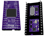
P1 QFP is to nice looking to hide underneath.
The idea is that the dip sockets machined pins rim works as smt pads.
Most pins are brought out, some have additional features.
P12 DAC/REF
P13 8bit 500K spi ADC
P14 8bit 500K spi ADC
P15 I2C clk fastmode+ (2.2K pullup)
P16 I2C data fastmode+ (2.2K pullup)
P17 SPI clk (2.2K pullup)
P18 SPI mosi (2.2K pullup)
P19 SPI miso (100K pullup)
P20 SPI CSn_0 internal to ADC (100K pullup)
P21 SPI CSn_1 (100K pullup)
P22 SPI CSn_2 (100K pullup)
P29 LED shared with internal eeprom sda.
The ADC is the cheapest 2channel at $1, they probably have drop in replacement for 12bit and/or 1MHZ for a little more.
https://www.mouser.com/datasheet/2/256/MAX11661-MAX11666-101409.pdf
I'm sending away for 9 pcb (0.8mm 2layer) today, 100's probably three weeks later for ~$25.
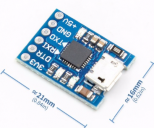
Free China CP2102 "Prop plug" included.


Comments
Machined pins at 0.5mm is the way to go, using a dip socket I also get a free carrier.
And female to male unlimited stacking!
Attached is a 3D PDF if you want a fly through.
I assume that these will be for sale? If so, put me down for a couple. :cool:
So do you reflow this, onto the top of the machine-pin-sockets ? I've thought about that in the past, but never set up to actually try it...
Would a castellated/plated edge make that easier to inspect / repair ?
We have used standard DIP sockets, stacked after the machine pins, as a lower cost sacrifice component, as the machine pins can be prone to snapping off...
Did you look at the ~25c MCUs like N76E003AQ20 ( or N76E003AT20) ? - 8 Ch 12b ADC with i2c
But still a lot of surface and 28pads holding it down at the same time and some solder should seep up the wall too.
I have a e 80% circle solder past on that surface area, so the plan it goes in the oven with the other parts.
As pcb is exactly the same size as carrier, it is easy to align up.
I don't' think I will not dabble with firmware on cheap mcu thought they actually cost less than stand alone adc.
This 12bit 2MHz is a drop in replacement for deluxe version of Stacker:
https://datasheets.maximintegrated.com/en/ds/MAX11102-MAX11117.pdf
You have 14 pins down the left side of the socket but there are 15 PIN numbers silkscreened. It looks like P7 isn't connected, or are two pins tied together on the bottom layer?
Have you considered a DIP32? That could give you external access to 4 more pins. How many would that leave without an internal or external function?
Or even a DIP40 with as close to the original Propeller pinout as possible, while keeping your additional parts?
P11 is now internal only, it is used with P12 for a 2bit resistor-DAC for ADC-REF, better than noisy PDM.
I also added pads for optional 3.3V LDO, though you're suppose to supply 5V and 3.3V externally
but if the need comes up where you only have 5V.
Yes, it's somewhat nuts that small MCUs cost (much) less than ADCs/DACs now !
If your focus is on better analog (which seems a good idea to differentiate), you can get a 3x3mm MCU with 12 x 12b ADC and 2 x 12b DAC for 67c/1k
That specs 1Msps/10b and 350ksps/12b ADC - getting close to that deluxe version ...
The MCU also comes in 4x4 QFN and TQFP32, for a few more cents, and I might try to fit the TQFP32 for lazy manufacturing tolerance.
This MCU can also output a 2% 49MHz/2N sysclk, to cover 4.9MHz, 6.125MHz, and it can manage DTR reset pulse, so the BOM could slash if you wanted it to...
If using that, I'd add an Oscillator footprint, to allow the 'deluxe' variant to have precise clocking option.
-Phil
I think it is way longer than needed if it's a 1.6mm pcb board it's intended for?
-Phil
I find an Asian drawing that specs 7.5-4.7 = 2.8 mm pin length, so is slightly shorter. I also found a web comment re breadboards that 0.1" sq pins were too short, but 0.126 (3.200 mm) was ok
I tried it in two different styles of breadboard, pushing it in as far as I could. In one with smaller recesses, the shoulders did not fit all the way into them, but the socket still seemed to seat firmly.
-Phil
YES, TONY!!! Someone gets it! Machined pins are always cheaper than replacing a wrecked breadboard. I have happily paid the difference for these many times. It's also why my favorite EVK has generally been from TI because they include these and if I need more, there is always digikey or Avent or Mouser.
There is a series called Oupiin 8004 that has a greater stack height if required. On those, the actual fine pin length is more like 4 than 2.75mm indicated on drawing.
Thinking about this some more, skipping a pin could be a pain, eg for someone wanting to connect to a Parallel LCD, 16b Data bus ?
Can the upper-pins, (not connected) be used for things like ADC-REF.
( Note with using an MCU ADC, the VREF is included).
https://www.mouser.com/Semiconductors/Power-Management-ICs/Voltage-Regulators-Voltage-Controllers/LDO-Voltage-Regulators/_/N-5cgacZ1yzvvqx?P=1z0wa2eZ1z0z33q&Ns=Pricing|0
P11 and P12 are merged as R/R2 so there is as way to decode back if you really want it, but a 0.1uf is attached so slower response.
Running out of space on a 2layer board to pick and choose what pin goes where.
After the first 9board for testing I maybe start from scratch again and make sure P0-P15 are pure gpio, but who want to waste 16pins on data bus, when there is 1MHz I2C/QSPI.
If you do a respin, then if you can fit in a QFN24(3x3) or QFN32(4x4) or TFP32 MCU, I can run up some i2c-ADC etc code.
Your ADC choices are 12 x 12 or 12 x 14 bit, and you can even have 2 or 4 12b DACs, which makes for a nice higher performance analog solution.
Also possible on this MCU is a 5MHz or 6.25MHz user choice of CLKout for Prop clock (removes the XTAL).
Pin count is an interesting question.
Checking lcsc.com, I can find 32 pin machine sockets DS1001-01-32BT1WSF6S-JKB for 100+ $0.2965, but no 28 or 40 pin ones. To me, 32 pins is better than 28.
If this jumped to 40 pins, then the logical step is to clone the FLiP pinout - but it seems to make more sense to not duplicate FLiP, but rather expand into areas FLiP does not cover ?
First test did not work, but now all pins make contact just say that is my trade secret
Stackable, It did need some harder pressure to be convinced to stay down.
Swiss made preci-dip sockets.
3.5mm length would been perfect, but 3.17mm is snug.
I will announce a paypal link next week for the 8 hand-made founders edition.
64K eeprom,
10bit adc dual channel with 3.3v, 2.2v & 1.1v selectable reference (e.g the 1000 step granularity can be between 0v-1v)
from a P2 thread..
Would that soldering work on these machine screw sockets ?
https://www.mill-max.com/assets/pdfs/090.pdf
The P2 talk wandered onto DIP modules & special packages to get that.
However, there are standard 0.9" DIP 64 sockets (from 68000 legacy tooling ?) that will (just) fit the standard P2 package.
Digikey also shows 0.9" 50 pin, but that is probably far too niche.
Overall DIP64 length is larger than it really has to be, to fit a P2 support, but it will help with cooling and save a heatsink
Using PcbNew to guide price corners, it seems 4 layers, 0.25mm via will allow TQFP100 to fit in the tramlines ok.
Attached is a routing /physical rough proof of concept for a FLiP_P2_64P
Addit: as well as the 0.9" sockets, ebay shows strips too...
50Pcs Single Row 40Pin 2.54mm Round Female Pin Header gold plated machined $10.68
50Pcs Pin Header Single Row 40Pin 2.54MM Round Male Gold Plated Machined $20.35