Shop OBEX P1 Docs P2 Docs Learn Events
New Product: Laser Ping Mount — Parallax Forums

New Product: Laser Ping Mount

PublisonPublison Posts: 12,366
edited 2018-05-24 21:38 in Robotics
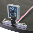
Nice little mount with holes for Arlo or similar, and holes spaced for servo horn for a LaserPing DAR!

https://www.parallax.com/product/725-28041
1000 x 1000 - 89K

Comments

  • Phil Pilgrim (PhiPi)Phil Pilgrim (PhiPi) Posts: 23,514
    edited 2018-05-25 23:55
    Nice! When Parallax does something, they do it right!

    -Phil

  • WhitWhit Posts: 4,191
    Amen, Phil. This is a great addition to the Parallax line.

    Have you played with the LaserPIng)))? It is fantastic.
  • Whit wrote:
    Have you played with the LaserPIng)))? It is fantastic.
    I have to admit, I have not. I definitely need to.

    -Phil
  • Phil
    Nice! When Parallax does something, they do it right!
    “Perfection is achieved not when there is nothing more to add, but when there is nothing left to take away. -Antoine de Saint-Exupery

    I would have to say that the etching and millwork cutout are unnecessary and surely drove the price up, but it does look nice :)
  • I would argue that the recess is necessary to protect the sensor from a hit to a wall.
  • The "etching" is actually engraving, part of the machining process. (You can see the tool marks.) The recess permits the cable socket to rest on the housing, instead of hovering above it -- much neater that way!

    -Phil
  • Phil & Publison

    :)

    I must admit that it is a nice looking part, but I would be willing to bet that it would work perfectly fine without the recess or "engraving".

    :)

    Nice job Parallax.
    Maybe all you really needed was a wire-brush battery post and terminal cleaner. :)

    Just pulling the chain a little :)
  • I like the way they look on the Stingray.
    2336 x 1316 - 1M
  • Publison wrote: »
    I like the way they look on the Stingray.

    Collector's Edition product setup right there, Jim.
  • PublisonPublison Posts: 12,366
    edited 2018-06-02 14:55
    The translators do not like the Laser PING))) running at 5 Volts on the Stingray. I tried to induce a little impedance, (5K), like we had to do with servos, but this did not work. The Prop does not see the Laser PING))). I'll experiment with other resistors.

    I set up all three Laser PING))) at 3.3 VIN, disabled the translator, and did a direct input to Pins 0,1,2. It runs the Stingray Demo program fine.

    Whit. It will not run your 1.5 demo. Are your PINGs 0,1,2, (right,center,left), when looking from the back wheel?
  • WhitWhit Posts: 4,191
    @Publison - LaserPINGs))) do look great on the Stingray. On the attached code - Connect the left-front Ping to Pin three, the center-front Ping to Pin two, the right-front Ping to Pin one. (At one time I had Pings on Pin 0 and Pin 4 - to explain the current placement) Parallax Serial LCD 4 X 20 is connected to pin 16 on Prop Robot Control Board.

    Let me know if this helps!
  • Whit wrote: »
    @Publison - LaserPINGs))) do look great on the Stingray. On the attached code - Connect the left-front Ping to Pin three, the center-front Ping to Pin two, the right-front Ping to Pin one. (At one time I had Pings on Pin 0 and Pin 4 - to explain the current placement) Parallax Serial LCD 4 X 20 is connected to pin 16 on Prop Robot Control Board.

    Let me know if this helps!

    I see thee errors of my ways. :)

    I see now that Pings are setup for P1-3 in your setup
    PRI Pings | i, Ticks
    '' Runs in a seperate cog
    
      'continuously read in Ping distances
      repeat
        repeat i from 1 to 3
          Ticks := Ping.Ticks(PING_PIN + i)
          Distance[i] := Ticks   
          Ticks /= 104
          Ticks <#= 96
    

    I had it set up for P0-P2 based on the original Ping with Stingray program.

    All is good with the world.

Sign In or Register to comment.