WS2812 Neopixel hubexec routine critique
 Peter Jakacki
Posts: 10,193
When something ain't broke, you shouldn't fix it, but then again it is fun fixing things, so let's break stuff. This is what I did with my WS2812 Neopixel routine since I wanted to tighten up the bit timing even though it always seems to work. I've found that REP instructions don't like branches or nesting and RDFAST won't work in hub exec, fair enough, but they would have been nice, so what can I do? The code posted works well, and the timing is pretty good too with inter-led timing maybe off by 50..100ns or so.
Other than putting this code into hub or even LUT RAM with a RDFAST, I'm just wondering if anyone has some ideas at improving it?
This is the code used to test it.
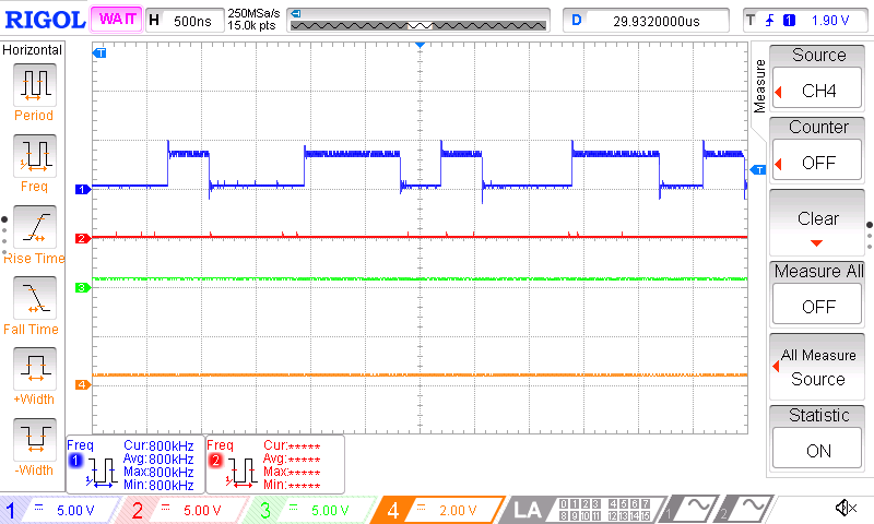
Here is the last 0 bit transmitted for an LED followed by a 1010 pattern for the next LED to show up any problems with timing.

Other than putting this code into hub or even LUT RAM with a RDFAST, I'm just wondering if anyone has some ideas at improving it?
CON
	wsdly	= sys_clk/2500000
DAT

' WS2812 ( array cnt -- ) pin is in cog "pinreg" - line RET is done at HL, not here
' 171207 version reads longs for each LED but only sends 24-bits (change to 32 for WRGB)
' Will transmit a whole array of bytes each back to back in WS2812 timing format
' line idles low and resets/synchs with low =>50us
' A zero is transmitted as 400ns high by 850ns low (+/-150ns)
' A one is transmitted as 800ns high by 450ns low HHL
WS2812	      mov	PTRB,tos1
	      sub	PTRB,#1  	'aligns 24-bit values when a long is read
.l2	      drvh	pinreg          ' start early as part of looping for each LED
              rdlong   	X,PTRB++        ' read next long
	      skip	#%110   	' skip delays for 1st bit sent for each LED
              rep	@.led,#24
.lp           drvh	pinreg    	' always clock tx pin high for at least 400ns
              waitx	#wsdly-8        ' 400ns
.l1           shl       X,#1 wc         ' get next bit
              drvc      pinreg    	' output data bit
              waitx	#wsdly-2        ' delay again, (data is either high or low)
              drvl	pinreg    	' always needs to go low in the last third of the cycle
	      waitx	#wsdly-18
.led          djnz     	tos,#.l2        ' read the next long as long as we can (tos = count)
.end          jmp       #DROP2          ' tx line left low to synch - discard stack parameters, all done.
This is the code used to test it.
$1.0000 == ledbuf
21 PIN
pub LED! ( color led -- )	4* ledbuf + !
pub SHOW			ledbuf 40 WS2812 ;
Here is the last 0 bit transmitted for an LED followed by a 1010 pattern for the next LED to show up any problems with timing.


Comments
A code-style comment around REP, is I prefer
Led_Bits EQU  24    ' RGB 24b
'Led_Bits EQU  32    'WRGB 32b

              rep	@.led,#Led_Bits
...
.led
        djnz     	tos,#.l2        ' read the next long as long as we can (tos = count)
which makes it clear the djnz is not included inside the REP.
Using SKIP is a good way to nudge the code, but it does not make it Clock tolerant.
ie if you vary sys_clk here, wsdly scales, but SKIP does not.
Also, if there is jitter in the rdlong X,PTRB++, due to slot timing, it would be nice if a WAIT could 'fix that'.
What are the clock limits of this code ?
- fastest and slowest sys_clk allowed ? - always good to include that comment in library code.
There was a web page out there, where someone pushed the timings around on the LEDs to see what was actually needed.
As would be expected, some timings are more tolerant than others.
FWIR, the sample is just an inbuilt monostable from the leading edge, which means leading hi should not jitter, but trailing low is more tolerant of jitter, and only needs to be safely inside the reset time.
Here is a simpler version though whereas the previous version was an exercise in achieving timing "worthiness" while utilizing newer P2 instructions. As it is I think I will stick with my simpler version based on earlier code but using RDLONG instead of RDBYTE. The timing is very tight and only the low between 24-bit transmissions is increased by an inconsequential 400ns.
btw, this routine doesn't waste time generating a 50us reset pulse since leaving the line low between calls is normally >50us anyway and if for some reason it was being called as fast as possible then it is easy to insert a short break in high-level code where it is easier to manage.
CON wsdly = sys_clk/2500000 DAT ' WS2812 ( array ledcnt -- ) pin is in cog "pinreg" - line RET is done at HL, not here ' Will transmit a whole array of 24-bit words each back to back in WS2812 timing format ' line idles low and resets/synchs with low =>50us ' A zero is transmitted as 400ns high by 850ns low (+/-150ns) ' A one is transmitted as 800ns high by 450ns low HHL ' The low period between each led is about 400ns longer but inconsequential WS2812 sub tos1,#1 ' offset for 24-bit long alignment .l2 rdlong X,tos1 ' read next long add tos1,#3 mov r1,#24 .lp shl X,#1 wc ' get next bit drvh pinreg ' always clock tx pin high for at least 400ns waitx #wsdly-4 ' 400ns drvc pinreg ' output data bit waitx #wsdly-4 ' delay again, (data is either high or low) drvl pinreg ' always needs to go low in the last third of the cycle waitx #wsdly-20 djnz r1,#.lp djnz tos,#.l2 ' read the next long as long as we can (tos = count) jmp #DROP2 ' tx line left low to synch - discard stack parameters, all done.I think REP is fine to use for libraries, as that saves a line of code, and frees one register, but I would be more wary of SKIP.
This web page
https://wp.josh.com/2014/05/13/ws2812-neopixels-are-not-so-finicky-once-you-get-to-know-them/
says t0h 200ns min, 350ns typ, 500ns Max, and 6000us for the reset.
t1h is > 550ns so looks like it monostable samples at ~ 525ns +/- 5% ?
and this web page includes WS2812B, and has slightly differing threshold conclusions
https://cpldcpu.wordpress.com/2014/01/14/light_ws2812-library-v2-0-part-i-understanding-the-ws2812/
563ns -> 0, and 625ns -> 1 , with Reset > 8.95us
What is the sys_clk range supported by this code ?
The best library will be the most clock speed tolerant.
BTW, I don't think there is any real change in the B timing, and the way that they present those timings never really shows the ratios. It's as if the receptionist formatted the chart and specs, rather than the designer.
I would simply format it like this from the programmer's viewpoint and then have the tolerances etc elsewhere.
The TH+TL=1.25us+/-600ns is not really right, as the TH clock+data bit doesn't have this tolerance, but TL certainly does.
Actually, it will work over a range of sys_clks, even for a fixed compile constant.
With a min of 200ns and Max of ~ 550ns, you can accept a ~2:1 clock range.
Of course, but even compile-time-constants have their limits.
As sys_clk reduces above, those WAIT values will shrink, probably until they wrap. (does that give a warning/error ?)
The code-transit times also increase.
eg 160MHz looks ok, as does 80MHz, but 50MHz hits the waitx #wsdly-20 threshold, and a 20MHz HRC is going to fail that WAIT, but 20MHz HRC code should be possible, as 16MHz AVRs can do this stuff....