Piezo amplifiers
 geo_leeman
Posts: 190
Hey all,
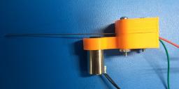
I'm working up a sensor that measures the resonant frequency of a bit of wire using a piezo element (see attached photos). The wire is "plucked" by the electromagnet below it and freely resonates. The idea is that as mass accumulates on the wire (freezing water) the resonant frequency will be reduced. This type of sensing methodology has been used in the past, but I'm afraid I'm overcomplicating the signal conditioning here. All I'm interested in is the frequency response to the plucking, so greatly amplifying the signal to the point of a square wave, then counting crossings seems more sensible that full FFT, etc.
That being said, I've considered and played with instrumentation amps, JFETs, and JFET based op-amps like the TL071 and a circuit like this. Any thoughts on the best/cheapest approach here (disposable sensors)? I know I'm overthinking/complicating the situation as it's not really precision instrumentation and I'm fighting the urge to properly DC offset, etc. For what it's worth - I hooked it up to an INA128 setup on a dual supply and got nice results with gains of 1-5k. This circuit will be signal supply in it's final state though.
Any thoughts appreciated!


Comments
-Phil
Bean
Ah, the genius of Bean-ius! I like that!
"Pluck and sense" reminds me of the use-every-letter-typing-practice-sentence:
The job requires extra pluck and zeal from every young wage earner.
-Phil
What is the frequency range observed for the ice sensor?
Vibrating wire instrumentation is commonly used in high accuracy geotechnical instrumentation. GEOKON is one major supplier. It does use the electromagnet both to pluck the wire and to return the signal, and the electronics can be sophisticated.
Yup. That's the reason I asked what micro he was using. If it were a Propeller, he could do that with a couple resistors and a cap -- no external amplification needed.
-Phil
I don't think it'll be a problem as long as I leave an ~1/8" gap. We're not talking about massive accumulation (we think).
I'm liking the idea of a single pickup/excitation device. I dug through the bin tonight and all I've got is an M74HC4049 which doesn't look like what I want. I guess its time for a digikey order. I like that sort of solution though as I'm not so dependent on lots of resistor/cap values on the BOM and not dealing with temp coeffs of all that.
To be clear, your thinking a cap and resistor in series to the input of the first inverter, chain a few inverters, then have 20M from the output of the last inverter in the chain to the input of the first? Like figure 6: https://www.fairchildsemi.com/application-notes/AN/AN-88.pdf
You could try that circuit, but instead of 1M at the input, just make it zero ohms--Feed the signal directly to the CMOS input though the capacitor. At 5V Vdd, the overall open loop gain could be over 100dB. A hitch is that the input impedance is reduced by the open loop gain, so the performance with a high impedance piezo pickup might be disappointing.
Better to make the gain in stages, with each stage built around a single inverter, and the stages capacitor coupled. The first stage should be lower gain so as to achieve higher input impedance. Subsequent stage or stages could drive toward the rails. Say x10 in the first stage, then full 40dB, x100 in the second stage, that gets you to the x1000 factor that you mentioned in the first post.
You have a 74HC4049. That should work. My first choice would probably be an CD4007, which is a kit of complementary mos transistors that you can hook up as inverters or in other ways that are good for special linear circuits. There is a nice writeup in this Nuts and Volts article,
fet_principles_and_circuits.
There is even a nice front end stage there, a high impedance source follower.
Of course high gain circuits can oscillate :~( so layout is important. Or close the loop, the wire as the resonant element in an oscillator.
I know that this approach works with pvdf piezo sensors into the Propeller sigma-delta inverter; piezo directly to the summing junction with feedback thru a high-ohm resistor.