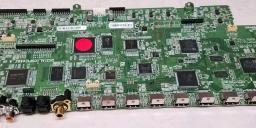
Finding excessive load on large circuit board
Hello All,
I recently acquired a Denon AVR-3313CI A/V receiver that is not working properly. I traced down the malfunction to there being excessive load on the 3.3v circuit pulling the voltage down to around 1.5v and causing the DC-DC converter to get overly hot. I unsoldered the two zero ohm resistors that connect the converter to the rest of the circuit and the voltage came back up to 3.3v. Is there any way to trace down the cause of the excessive load or is the unit trash? I was thinking maybe use a thermal camera to see what components get hotter than the rest.
Thanks,
Bryan


Comments
It was the only thing glowing in comparison to everything else on the board.
For this particular unit, the power supply kept shutting down and retrying, making the shorted component hot enough to see, but not noticeably warm to the touch.
Another way to trace is with a precision voltmeter (like 6 digit). Or with a less accurate voltmeter and a DIY battery powered amplifier. Trace the voltage drops from the source to known power pins on the ICs. In general, the greatest voltage drop will be near the fault. That works best if the board has kind of a star layout and is much easier if you have a schematic and layout diagram.
Do check with a multimeter in first the ohms and then the diode position to see if the effect is a pure resistance or if it is a has a threshold. The 1.5V reading suggests a diode drop. Even better, use a current limited variable supply and increase the voltage slowly to see at how the current increases with voltage, linear, or at a threshold. A dead short will be linear, trace resistance only.
I just wanted to give an update on the A/V receiver. I used the thermal camera and found the HDMI switching IC to be causing the excessive load. I swapped the IC from another board I had (the other board had corrupt firmware) and the unit has been working properly for over 8 months. Thanks for all your help.
Bryan
Also looks like a great soldering rework job on that chip.
...ditto that!
It's always nice to see the follow up.
i have a problem similar to yours..you managed to solve ..?