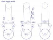
Anyone with load cell experience with Prop?
I want to experiment with a load cell. A main pulley has a belt with a fixed tension on it for example 50LB. When the main pulley is turning it will lift a load of approximately 125lb. The belt under load will then have 50 + 125 = 175lb on it. I want to measure the force against the idler pulley for both sides of the system and have the prop read the load and evaluate for problems. I see tons of load cells on line, does anyone have any experience with something more industrial for this application? I need something very reliable. I am working on trying to find out the formulas for determining the force against the sensor.


Comments
Many reputable Load Cell manufactures (Omega Engineering, for one) sell mating digital readouts, ready to go and calibrated (load cells are not linear devices)
http://www.omega.com/pressure/pdf/LC101.pdf
You can give it a 10VDC supply and it gives +/- 30mv output max, linear output at 3 mV/V. I would need to convert the +/- output to a positive output with a center at 5V, then 0 and 10V is each extreme.
I could not get info from the tech on the life expectancy. I would like to get 10 years life.
Any thoughts on this approach? Any better ideas to get the force on the swivel plate into a Prop? This seems workable but I really don't want to spend the time building a PCB and working out the op amp/gain/ d to a, but I see no way around it. He said use the differential input on an op amp, not single input as the device has differential output. I have done some op amp gain on other sensors like current sensors and after some tweaks I can get it but it is not my forte. Ideally I would build a Prop board dedicated to the sensor, and set a max upper and lower limit for it to fire a simple 3v3 output on overloads. Then the main board( already over taxed) can just look at the sensor as a simple limit switch.
You can also buy all forms of load cells on e-bay. The ones I have bought come with a specification sheet. This shows the gage resistance and the ratiometic full scale output. You can electronically calibrate the output by shunting a bridge arm with a precision resistor. Micromeasurements [maker of excellent strain gages] has, on their web site, some good information; including calculators for determining the value of shunt resistors. For example: if the bridge uses 530 ohm gages & the stated output of the load cell is 2mV/V, then to simulate a full scale load output a 43,xxx ohm shunt resistor is called for [don't remember the exact value].
I presently use INA 125 amplifiers; and am looking into a HX711 24 bit converter.
Hope this helps.
cheers, David
cheers, David
For reading them, you won't do better at the hobby level than a HX711. They're cheap, easy to use, and as accurate as you need for most systems, and you can get breakouts cheap on eBay and (less cheap) from SparkFun. They're not NTEP and don't support sense leads, but it's find as long as the cable between the ADC and the sensor isn't more than ten or fifteen feet long. (Sense leads feed the excitation voltage back from the cell to the ADC so it can compensate for the voltage drop.) Every better ADC I've ever looked into is massively more difficult to use as well as much more expensive.
Looks like someone has put an object here
http://obex.parallax.com/object/731
Here is the sparkfun BOB
https://www.sparkfun.com/products/13879
I could use two of these and not have to deal with +/- output conversion?
https://www.sparkfun.com/products/13331
I will order these and at least get some understanding but I don't see why two of these single sensors wont work as well as the S type with tension/compression voltage output.
Have you thought of just simply "encoding" the deflection angle of your idler plate?
I presume all you need is biliteral overload trip points, and this could easily be done digitally with two opto interrupters, or several optos per side for several trip points.
All digital, no op amps.... easy peasy.
Cheers,
Peter (pjv)
Yes that was my first idea as I have done that before. However, in this application once installed it will not be accessible, or will be a challenge to access it if springs needed adjusting after the fact. So my thoughts were put a load sensor of some sort where the swivel plate does not move at all, it just puts pressure on a sensor or two sensors as mentioned. Run the wires out of the area to the accessible area, then any changes would be in software, not mechanical.
The idea with springs is, you set the motor in motion lifting the object, set the springs to allow for the switches to not be pressed under normal conditions. But, the springs may be pressed at startup. This is sort the same idea of encoding but using switches.
I'll give that some thought though, I am looking for the simplest most reliable solution.
If I remember correctly it has two frequency outputs, the delta is the load.
They were pretty easy to use the P1.
Bean
Any thought on how you will calibrate it?
I have a 100 lb S shaped analog load cell from Omega, and
I used to calibrate it with 3 different weights. I don't know
how accurate you need. Mine was lightly preloaded in
compression, but I could have reversed direction and used it
for tension too.
Bill M.
Calibration for small loads (up to 25Kg) in tension was done with a set of certified weights. Higher loads were done with certified load cells that could calibrate for tension and compression. All of the weights and load cells used were calibrated yearly by a NIST certified lab.