Linear acuator limit switch questions
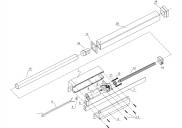
This device has two wires to drive it, just reverse polarity to go the other direction. It shows a limit contacts at #14 a Limit Switch Bar at #7. Since the device stops working in each direction when it hits the end of travel switch area, and since it can still reverse, this means they are using some diodes in the limit scheme to stop the flow of current in one direction only. I want to use the device in conjunction with other motors and this one needs to complete and be sure it completed before proceeding. I was thinking the power to the actuator for one direction could be a DPST relay that connects both GND and +V. The device will have a known travel time, so the Prop could tell it to move by setting the relay, then wait until slightly after the known travel time to turn off the relay. Once the device hits the limit I am assuming that no more current will flow in that direction and then it could be possible to switch in a +V on the same + side we were just using on the relay and check of a voltage on the other wire of the actuator. If the device has arrived then the path will be completed and the prop can see the voltage ( maybe use a divider and still use 12V). If the voltage is not present on the test then shut down and warn of a fault. There is no other easy way to rig up another switch or sensor to detect the travel completion in this application and I thought why not use the built in diode/limiting scheme. Since I don't have that device I was wondering if this logic makes sense.


Comments
If you remove the end cap #19 and can see the end of the lead screw, you could drill and tap the end of the lead screw and install an extension shaft for an encoder.
Let's assume that it is a 1/2" lead screw. You could drill and tap it for 10-32 threads. Then insert a high precision shoulder bolt with 10-32 threads, 1/4" shoulder, and a 2" shoulder length. Cut the head off, drill the end cap, and install a rotary encoder. Mount a slotted optical switch to the end cap.
Doesn't sound too difficult, providing you can see the end of the lead screw.
https://mcmaster.com/#94035a189/=177m0x7
EDIT: On the other hand, if the lead screw is hardened, then I would definitely look for an alternative.
Zero current tells you if it is at one end or the other. Polarity to the two wires should tell you which end.
(In the next post. Dang forum software!)
The two diodes in parallel with the limit switches are part of the assembly. The other four diodes form a bridge that provides an output that's high (at motor voltage) when the motor is running, zero, otherwise.
-Phil
"Yoyo" / "Stringpot" Encoder
Yep, I tried to add a linear slide pot and no go. $30 w/out feedback, $130 w/ feedback. I don't like the idea of an encoder on the motor shaft, I would want absolute position without having to home anything.
There are still some options I'd like to try. I ordered a flex sensor, I'm going to try to add that. If the actuator is all the way to the "left" there would be no flex, as it gets closer to the right end stop, there would be max flex. I hope it works.