Need advice from math gurus: ballscrew>sprocket>chain force
I am experimenting with something and need to sort out the loads on the chains to adjust a sprocket ratio at the motor I am using to be able to provide enough torque. I never have tried any calculations like this. I want to first calculate how many lb's of static force would be on the chain assuming for simple math a 2" OD chain sprocket and a 3/4" ball screw with Lead = .25 ( 4 turns per inch travel). Basically under the load, how much lbs is required to hold the weight suspended if I were to reach out a grab the chain. If I can get that then I can sort out the rest ie type of chain to support load, motor torque in oz-in etc. I am trying to first understand what are the factors to consider to arrive at the load on the chain between the two ball screws supporting the load.
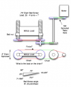
The image shows a simplified design. Two ball screws support the load. A chain is attached at the bottom on 2 sprockets that for now are 2" OD.
The image shows a simplified design. Two ball screws support the load. A chain is attached at the bottom on 2 sprockets that for now are 2" OD.


Comments
That means you take some arbitrary small movement of the load, then calculate how far the driver moves to cause that.
That distance ratio, is the inverse of the force ratio.
The diagram looks a bit like a tensile tester. Is that what you are building?
Glad to help. That's a big piece of glass. Must be fairly thick to be 600 lbs. About 0.75" or so?
JMO
Ah, yes, I do a lot of actual load-sensing/torque-limiting via monitoring/limiting of the PID output. However, I always spec my drive-train components beyond the power of the motor. You could always limit the motor torque or use a torque-limiting coupling between the motor-shaft and the reducer(?)
Worm reducers are great for high ratio situations but they do have a down side. High friction, high heat generation, and high wear unless it is a ball screw worm gear. Not too much of a problem for intermittent operation but the heat generated by continuous operation will break down the grease and damage the gears.
Not a fan of chains, myself, because of stretch issues. Have you looked at belt-drive?
Seems very doable to me.
Cheers,
Peter (pjv)
Yikes, I was referring to toothed-belts/pulleys. The same as used on car-engines where overhead cam timing is critical.
There are belts for all kinds of loads, no noise, no lube required and no stretch.
I do like pjv's suggestion, although that would require at least 25psi of pressure. Not sure if 4inch ABS pipe would handle that. Might be worth buying a piece to test it though.
Oh yes. Definitely want something to keep it from coming crashing down if something breaks.
MrBi11's suggestion got me thinking about elevators and their counterweights. Have you considered steel cables and counterweights? That would require a much smaller motor and allow for somewhat faster movement.
I am trying to understand a mystery regarding torque. In one case if you have a pulley that is 10 teeth driving a 100 tooth then the ratio of torque should be 10:1. However the radius difference in the 10 tooth and 100 tooth sprockets is not 10x. If you connect a chain to a lever at 1" radius (as in a 1" radius pulley) then 10x torque would be the same as tying the chain to a 10" lever or equivalent 10" radius pulley for the same effect of torque = length * force. I am trying to find the discrepancy of radius versus teeth count. Torque = force * length. But it can also be represented as a ratio of teeth count, but teeth count is not linear with radius. The radius is smaller than 2x on a 20 tooth sprocket versus 10 tooth. It doesn't add up.
Circum is 2 * Pi * r, so that certainly is linear with radius.
The radius that matters on a gear, is the ~centre of the teeth, where they mesh, & that should ratio with teeth count, if they expect to mesh correctly.
The way I imagine this is that; the 600LB load might be present and then it might not so a fixed counterbalance might present a problem. I have used a pneumatic cylinder for this purpose, where I can apply, remove or regulate the air pressure. Blocking the ports also makes for a very effective brake.
Edit: I once used a rotary pneumatic counterbalance (with cable) but a quick look on the web didn't find one.
Edit: I see you have two ballscrews there, which are pure rubbing friction and very inefficient (much like worm gears), even if they are slathered in grease. Triple the calculated forces required for reliable long-term operation.
Actually, ballscrews have much lower friction than worm gears or acme screws, although higher friction than an equivalent geared transmission. Ball screws were used on gamma cameras to lift heads that could weigh over 3,000 pounds, and in tensile testers up to about 2000 pounds.