

New Figure 8 Challanger

I would like to introduce ‘zBot’ to the Parallax Forum community. I’ve been working on it as a winter project over the last few years. Last winter, I started working on zBot’s auto-pilot software. I need a test environment and chose the “Figure 8” challenge.
The robot I am developing is meant to operate in larger spaces (10 meters x 10 meters). It was never intended to be used to perform small accurate movements. For me, it was an interesting software challenge to coax the auto-pilot to behave correctly at this scale. On my ‘Still to Do’ list, I have now added the need for ‘Auto-Pilot Version 2’ that will do cursive writing.
Here is zBot’s 1st video. "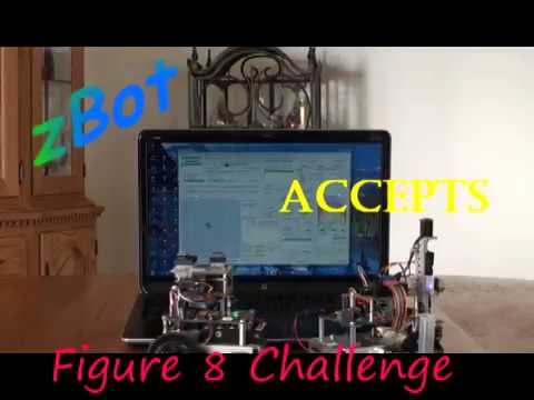 "
"
The robot I am developing is meant to operate in larger spaces (10 meters x 10 meters). It was never intended to be used to perform small accurate movements. For me, it was an interesting software challenge to coax the auto-pilot to behave correctly at this scale. On my ‘Still to Do’ list, I have now added the need for ‘Auto-Pilot Version 2’ that will do cursive writing.
Here is zBot’s 1st video. "
"
Comments
Can I fix it so all can see the vid.
Where can we learn more about it?
How did you post the video? Did you use the [ video ][ /video ] tags, or just post the URL? Maybe remove the surrounding quotes?
-Phil
BRAVO BRAVO BRAVO! That is utterly fabulous and a first, simultaneous F8s by multiple bots, heck, I'd call that a swarm!
Seriously great work, you have us all spellbound and wanting to hear more. Please post your video in the F8 Challenge thread too: http://forums.parallax.com/discussion/138125/erco-s-figure-eight-challenge/p19
When I first posted the video, I used the ‘YouTube” button and entered the ID # for the vid. In preview, all was well. After the post, my Windows PC could see the vid. On an Android tablet we just got a downloaded file. A quick forum search suggested using the long url. So I put the full “https …” in quotes and now all works.
Erco,
Reposted in the F8 thread as requested.
I never thought of two bots as a swarm. The software currently can handle a maximum of 20 bots, but I haven’t tested that limit yet. In the vid, there are two more chassis in the background ready to become bots. Maybe then I should upgrade to the P2 and dedicate a couple of COGs to swarm behavior.
Keith,
I thank you for your interest in my project. I am very willing to share the ideas and concepts that form the structure of this robot, but that in its self is a massive undertaking for any who wishes to understand this new paradigm of home-based robotic development.
The F8 challenge was my robot’s first public appearance. I hope by next fall to have web site describing the robot.
Keith, from your background, I see that you understand robots at a much greater level than just tinkering with hardware. What specifically are your questions?
-Malc
The following is a brief discussion of design concepts that under-lay the robot I have built and demonstrated in the top entry video. A fundamental criterion of my plan was that:
To that end, the first software-wrapper, written in Visual Basic (seen the ‘Figure 8’ challenge video) is an interface to a fleet of drones. The interface is built on a set of standards that removes idiosyncrasies found among drones constructed with different hardware. This has been accomplished by using the original design template for the personal computer of the late 1970’s.
"http://forums.parallax.com/utility/thumbnail/119660/FileUpload/59/bffefa9de707c371c79de79eae5d1e.png"
Putting aside your emotional feelings of who and what Microsoft is now, this Software-Hardware interface paradigm won the early PC design wars and was used for many years before better became established.
In the early years of DOS, we older code developers viewed DOS as having 3 layers. The lowest layer, ‘BIOS’ was an interface that theoretically guarantied, that our developed applications would run on any ‘DOS’ compliant hardware. The second layer gave developers large amounts of persistent off-line storage. The third layer has allowed human creativity to soar. Look what is being done today with software. It all started from simple ideas, brought to reality as someone’s garage hobby many decades ago.
In my “Home-Based Robotic Development’ environment, I have taken the original concept and modernized it a bit. It is important not to think of the above concept as a software platform but, think of it as a template to build a robot upon.
The first bit added was a “Packet-Based” BIOS-like set of calls across a network that interfaces a physical drone and the robot. In the above diagram, the following box would partially sit over the green ‘DOS’ box, completely cross the gold colored ‘BIOS Services’ box and replace the blue ‘PC Hardware’ box. This concept change now allows the creation of a robot where all its tools in the real world (insert your own drone ideas here) are managed and controlled by your robot application that runs on the digital device of your choosing.
"http://forums.parallax.com/utility/thumbnail/119661/FileUpload/58/5d775d52838c2e8aafbc8c4f01c352.png"
The reason chosen for using “Packet-Based” BIOS-like calls is that transmitted packets always receive acknowledgment packets. If a packet transmitted to a drone is saved along with its acknowledgment, then we have captured a ‘real world’ drone response to a stimulus (a BIOS-like command).
In my robot, the “Get A2D Temp” BIOS-like command packet will be acknowledged with the sensor reading and relevant information such as: Heading, Battery Voltage, XBee signal strength.
This “Packet and Response” is the basis of my second fundamental robot design criteria (see below).
The next bit I modernized is the concept of data storage and retrieval (part of the green ‘DOS’ box). In my robot, all collected data is managed as a simple precept of the real world. Information within that precept is available to guide and direct all active drones in the field.
If a drone is asked to perform an ultra-sonic scan, the results are analyzed; objects found are added to the precept, empty scan regions are added to the precept. In essence, the precept is an on-going/developing map defining the area where all online drones can safely work in.
For simplicity, I define a “Session” to be a collection of all BIOS-like calls (and their responses), made to any of the on-line physical drones or bots over a period of time. Usually a session will accomplish a goal. Now, if we save all packets (and the responses) of a session, we have a firm record of the steps taken by the robot in order to reach its session goal.
The second fundamental design criteria under pinning my robot is “The Saved Session”. A saved session has two purposes. If reloaded when an active fleet of drones exists, and the “Re-Run”, the drone will perform and respond at their top speed. We are re-playing a script to achieve a goal. This is how my drone attempting the “Figure 8 Challenge” were controlled.
The second purpose of a saved session is that it can be loaded by the robot when there are NO active drones. If the session or script is run, the robot experiences real-world feed back even though there is no real world activity. An example of this is seen at the end of my video when my robot thinks its drones are really writing cursive script letters.
As a software developer, this design feature has shortened development time of numerous features considerably.
I hope this description of my robot’s operation sheds some light on its basic operation as seen in the above video. The second software layer of my robot (I hope to introduce this fall), works exclusively building and managing the session’s precept. Dead reckoning navigation is replaced by Localization. Directed recursive scanning fixes the location of objects and generates command streams that in the end will have caused a drone to map an entire area. All space is mapped via a ‘Delaunay Triangulation’ variant. A modified A* pathfinding algorithm is used to generate the routes of drones. Plus many more wanted robotic features.
Malcolm