Reverse Engineering help
 TC
Posts: 1,019
Hello all,
I am reverse engineering a circuit, and I am trying to understand one part of it. I cant give any real details about what I am working on, so please bear with me.
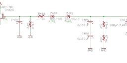
This circuit is coming from the secondary side of a transformer. I am having trouble understanding what could be the voltage after the 2 series zener diodes? And wouldn't transistor "Q402-TR1" just short out when the voltage on the base is high enough?
Could someone please help me understand what the engineer thinking.
Thanks
TC


Comments
Q403 is a current mirror. It sets the maximum current that Q402 can pass when it's turned on, in this case:
It would be helpful to see where that vertical wire goes, though, to facilitate a more complete answer.
-Phil
Ah... Now I understand.
I was wondering if it was a current mirror circuit, but I did not know for sure.
Here is the circuit that controls the transformer. Some of the values/parts could be wrong. The board is all SMD, and trying to figure out what the marking codes can be a pain. The input is coming from a IO pin from a micro.
I'm sorry, I can't give that information out. It is a prototype item. I am only reverse engineering it to learn what and why engineers do what they do.
Sure sounds like a Death Ray.
You figured it out. Muhahaha