Prop-based voltage comparator
 Phil Pilgrim (PhiPi)
Posts: 23,514
in Propeller 1
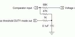
Most of us are familiar with the Propeller's sigma-delta ADC configuration and programming. It works quite well if you have time to integrate a reading over several clock cycles. But sometimes you want nothing more than a quick indication of whether a voltage is higher or lower than a given threshold. To that end, I've come up with a way to do this using the Propeller and a few passive components. Here's the basic configuration:
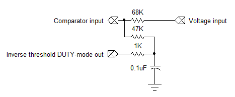
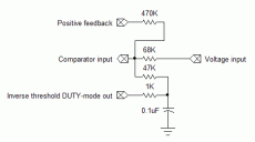
The Propeller generates a DUTY-mode signal that's filtered by the 1K resistor and 0.1uF cap to form a low-impedance voltage source. This voltage is combined with the input voltage at the summing junction formed by the other two resistors. If the resulting voltage is above the Prop's input threshold, a program reading the pin will see a 1; otherwise, a 0. The DUTY-mode voltage is actually the inverse of the desired threshold. IOW, suppose that both summing resistors had the same value, and that the Prop's input threshold was exactly Vdd/2. If you wanted a threshold of 0.25•Vdd, you would want a filtered DUTY-mode voltage of 0.75•Vdd. However, because the Prop's input threshold varies from Vdd/2, it's necessary to make the inverse threshold's summing resistor stiffer to accommodate the entire range of 0 to Vdd.
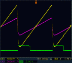
In order to test this scheme, I configured a counter to output the inverse of what it saw on the comparator input (mode %01001), so I could see it on my 'scope. I also programmed another cog to continuously sweep a voltage from 0 to Vdd in a sawtooth pattern via another filtered DUTY-mode output to simulate the voltage input. This is what I saw on the output:
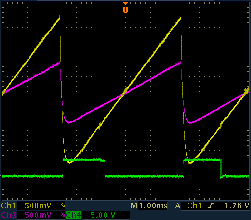
This was with a DUTY-mode frqa value of $8000_0000. The yellow trace is the input voltage; the magenta trace, the voltage at the summing junction; the green trace, the inverted output from the comparator. It looks pretty clean at this scale, doesn't it?
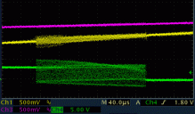
But let's zoom in on the comparator's falling edge:
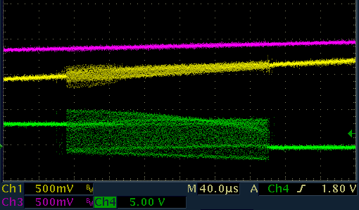
Just look at those oscillations! This is not an uncommon behavior for analog comparators whose inputs are slowly changing as is shown here. In this case, it's especially aggravated by the fact that all my passives were inserted into a solderless breadboard. Adhering to the same placement standards required by the sigma-delta ADC would've resulted in less noise and oscillation. Nonetheless, let's try to fix it.
The usual way to reduce or eliminate oscillation is to add hysteresis, which is just a little bit of positive feedback from the comparator output back to the input. Unfortunately the Prop's counters only have a negative feedback mode. There are two ways around this: 1) Add an external inverter to the negative feedback pin, or 2) add another counter-based inverter, thus using up another pin. For simplicity, I did the latter, as shown here:
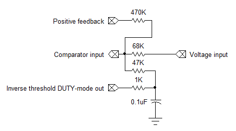
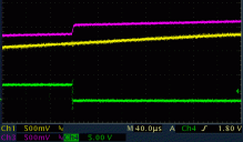
The 470K resistor adds quite a bit of hysteresis, but with my shaky breadboard setup, it's really needed to quell the oscillations. Here's what the output looks like with this circuit:
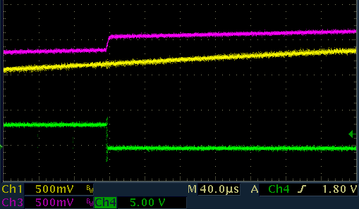
There are two things to notice here: 1) the absence of oscillations, and 2) that little bump in the summing junction voltage (magenta trace). The latter is caused by the doubly-inverted comparator output from the Prop adding a little voltage to the summing junction.
Here's the program I used to create these images:
Overall, I'm satisfied with the results. Given a PCB with SMT components placed close to the Prop's pins, the simple circuit (without hysteresis) that uses only two pins might be all that's necessary. The one part I left out was calibration: IOW, computing how the frqa values for the threshold's DUTY-mode output relate to the actual threshold voltages on the summing junction and the Prop's actual logic threshold.
-Phil
The Propeller generates a DUTY-mode signal that's filtered by the 1K resistor and 0.1uF cap to form a low-impedance voltage source. This voltage is combined with the input voltage at the summing junction formed by the other two resistors. If the resulting voltage is above the Prop's input threshold, a program reading the pin will see a 1; otherwise, a 0. The DUTY-mode voltage is actually the inverse of the desired threshold. IOW, suppose that both summing resistors had the same value, and that the Prop's input threshold was exactly Vdd/2. If you wanted a threshold of 0.25•Vdd, you would want a filtered DUTY-mode voltage of 0.75•Vdd. However, because the Prop's input threshold varies from Vdd/2, it's necessary to make the inverse threshold's summing resistor stiffer to accommodate the entire range of 0 to Vdd.
In order to test this scheme, I configured a counter to output the inverse of what it saw on the comparator input (mode %01001), so I could see it on my 'scope. I also programmed another cog to continuously sweep a voltage from 0 to Vdd in a sawtooth pattern via another filtered DUTY-mode output to simulate the voltage input. This is what I saw on the output:

This was with a DUTY-mode frqa value of $8000_0000. The yellow trace is the input voltage; the magenta trace, the voltage at the summing junction; the green trace, the inverted output from the comparator. It looks pretty clean at this scale, doesn't it?
But let's zoom in on the comparator's falling edge:

Just look at those oscillations! This is not an uncommon behavior for analog comparators whose inputs are slowly changing as is shown here. In this case, it's especially aggravated by the fact that all my passives were inserted into a solderless breadboard. Adhering to the same placement standards required by the sigma-delta ADC would've resulted in less noise and oscillation. Nonetheless, let's try to fix it.
The usual way to reduce or eliminate oscillation is to add hysteresis, which is just a little bit of positive feedback from the comparator output back to the input. Unfortunately the Prop's counters only have a negative feedback mode. There are two ways around this: 1) Add an external inverter to the negative feedback pin, or 2) add another counter-based inverter, thus using up another pin. For simplicity, I did the latter, as shown here:

The 470K resistor adds quite a bit of hysteresis, but with my shaky breadboard setup, it's really needed to quell the oscillations. Here's what the output looks like with this circuit:

There are two things to notice here: 1) the absence of oscillations, and 2) that little bump in the summing junction voltage (magenta trace). The latter is caused by the doubly-inverted comparator output from the Prop adding a little voltage to the summing junction.
Here's the program I used to create these images:
CON

  _clkmode       = xtal1 + pll16x
  _xinfreq       = 5_000_000

  RAMP_PIN = 0  'Pin for DUTY mode ramp output to simulate an input voltage.
  THLD_PIN = 1  'Pin for DUTY-mode inverse threshold output.
  COMP_PIN = 6  'Input pin for summing junction.
  OUTP_PIN = 11 'Pin for inverted comparator output.
  HYST_PIN = 12 'Pin for hysteresis output (doubly-inverted comparator output).

VAR

  long stack[30]

PUB start

  cognew (ramper, @ stack)
  dira[THLD_PIN]~~
  ctra := %00110 << 26 | THLD_PIN
  frqa := $8000_0000
  dira[OUTP_PIN]~~
  ctrb := %01001 << 26 | OUTP_PIN << 9 | COMP_PIN
  repeat

PUB ramper | i

  'Cog to generate voltage ramp for simulated input.
  'Also uses a timer to invert the comparator's inverted output
  '  for hysteresis.

  dira[RAMP_PIN]~~
  ctra := %00110 << 26 | RAMP_PIN
  dira[HYST_PIN]~~
  ctrb := %01001 << 26 | HYST_PIN << 9 | OUTP_PIN
  repeat
    repeat i from 0 to 255
      frqa := i << 24
Overall, I'm satisfied with the results. Given a PCB with SMT components placed close to the Prop's pins, the simple circuit (without hysteresis) that uses only two pins might be all that's necessary. The one part I left out was calibration: IOW, computing how the frqa values for the threshold's DUTY-mode output relate to the actual threshold voltages on the summing junction and the Prop's actual logic threshold.
-Phil


Comments
Great job!
Of course what you have here is simply an ADC in disguise, and of course it could be used that way too I guess.
Even if we used a tiny cheap comparator such as a MCP6541 it would still need the RC for reference but the hysteresis resistor could at least be tied to the push-pull output of this comparator thus saving a pin. Sad thing though is that for a few cents more I can pick up a PIC12Fxxxx in MSOP8 suitably programmed which does all the A/D for me and sends it to me serially which is what I did in a recent project.
However, I love the RC solution and the way that you have presented it.
Cheers
You can achieve similar results with just a single pin which serves as the DAC driver when it is set to "output" (say 99%), and as the comparator sensor when set to "input"(say 1%). The math changes a bunch, but is easily handled in software.
This method is not as preferred as your approach, but when pincount is tight, it can be a viable solution. Of course it also serves as a one pin balancing A/D. Works great for non-demanding applications.
Cheers,
Peter
Always a First Class presentation !