PCBs for ADC Chips (MCP3208 and ADC124S021)
 Duane Degn
Posts: 10,588
I recently wired up an ADC chip (MCP3208) on a piece of perf board and I was again surprised how long it can take to make the needed connections.
To save myself the bother of wiring up one of these chips in the future, I decided to fire up DipTrace and design a quick PCB.
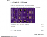
As you can see it costs $5.75 to have three of these boards made as OSHPark.
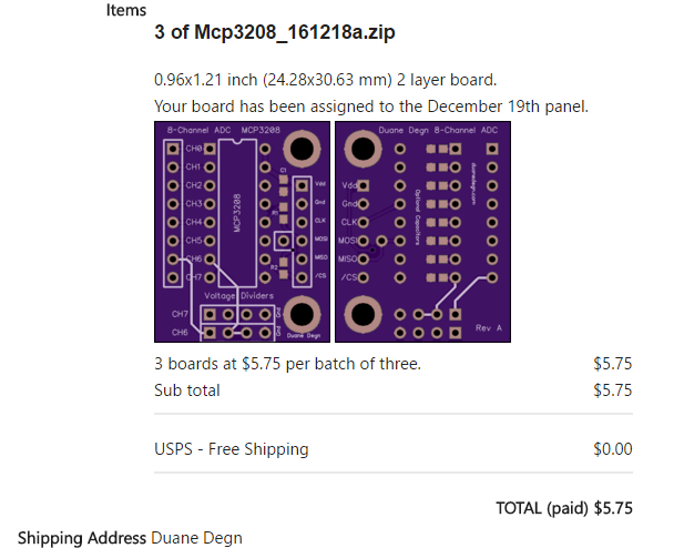
The MCP3208 chips I have on hand are DIP packages.
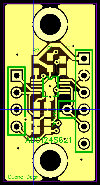
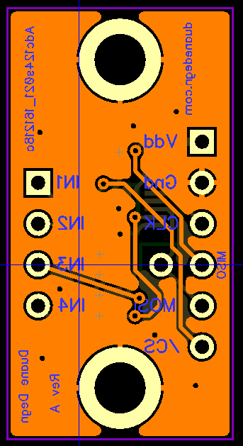
I also have some of the small ADC chips used in the Propeller Activity Board. This is the ADC124S021 four channel chip. I make another PCB for this chip.
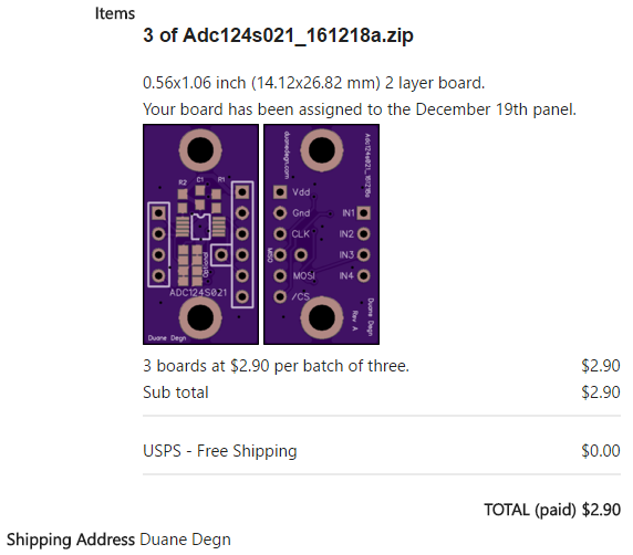
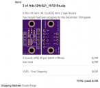
As you can see, this smaller board is just $2.90 for three boards.
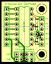
Both boards include a pin which will jumper the data out pin to the data in pin. This reduces the number of pins required to communicate with the chip.
The MCP3208 board includes a place to add a voltage divider for the last two channels.
Both boards include pads for adding capacitors to the analog inputs.
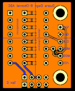
Here are the top and bottom layers of both boards. If any of you have suggestions on how to improve the board, I hope you let me know.
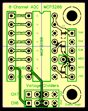
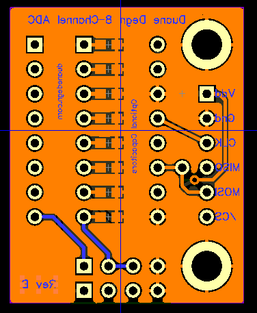
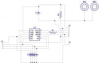
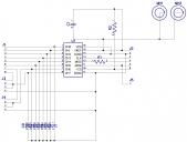
I've attached the zipped Gerber files and schematics for these two boards. These are the same Gerber files I submitted to OSHPark.
I haven't tested these boards yet. I'll update this thread once I receive and test the PCBs.
To save myself the bother of wiring up one of these chips in the future, I decided to fire up DipTrace and design a quick PCB.
As you can see it costs $5.75 to have three of these boards made as OSHPark.
The MCP3208 chips I have on hand are DIP packages.
I also have some of the small ADC chips used in the Propeller Activity Board. This is the ADC124S021 four channel chip. I make another PCB for this chip.
As you can see, this smaller board is just $2.90 for three boards.
Both boards include a pin which will jumper the data out pin to the data in pin. This reduces the number of pins required to communicate with the chip.
The MCP3208 board includes a place to add a voltage divider for the last two channels.
Both boards include pads for adding capacitors to the analog inputs.
Here are the top and bottom layers of both boards. If any of you have suggestions on how to improve the board, I hope you let me know.
I've attached the zipped Gerber files and schematics for these two boards. These are the same Gerber files I submitted to OSHPark.
I haven't tested these boards yet. I'll update this thread once I receive and test the PCBs.




Comments
I'll try to do so in the next day or two.
Here's a picture of the bare boards.
Did you ever get these boards built and tested?
Jim
I built them, and I keep thinking I'll use them in a robot and share a video of the robot in action as a report on these PCB. Obviously I haven't done this.
I'll give these a boring but quick test right now.
I tested the ADC124S021 using both MOSI and MISO pins.
The MCP3208 was tested using a single I/O pin.
Both boards have a place where a jumper can be added so the MOSI and MISO lines are shared with a single I/O pin on the Prop.
The MISO lines on both boards pass through R1 to protect the Propeller when running these chips at 5V. I used a 10K ohm resistors for all the resistor values.
Besides the MISO lines, there's also a resistor (R2) to pull the CS line high on both boards.
The last two channels on the MCP3208 pass through pins which may used as a voltage divider. If anyone has questions on how to use these pins (with appropriate resistors) as a voltage divider, let me know and I'll try to explain.
I'll likely make a breakout board for the I2C ADC used in the Propeller Board of Education.