"No Propeller chip found on any serial port. Scanned COM4."
Hello, I am getting the error message "No Propeller chip found on any serial port. Scanned COM4." when I try to Identify Hardware on a Propeller chip. The blue LED on the Prop Plug lights up, but the red LED does not.
I have done quite a bit of troubleshooting on this, and I've read many related threads on this forum. But I am unable to find the source of the problem, so I'm here to ask for help. Here is the situation:
I am working on a prototype circuit board which uses the Propeller LQFP-44 package. I have assembled a board with only the Propeller, four bypass capacitors (0.1 uF), a 4-pin header for the Prop Plug, and two wires connecting the board to an external regulated 3.3 V power supply.
I have verified the Prop Plug connections to VSS and the Propeller's RESn, P31, and P30 pins using a continuity tester. I have verified using a voltmeter that the Propeller is powered by 3.33 V. I have verified that the Prop Plug is working by using it to communicate with a DIP-40 Propeller I have installed on a breadboard. I have tried 4 different Propellers on 2 different boards.
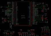
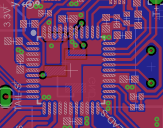
Considering all this, it seems clear there is a problem with the custom circuit board I designed. But as far as I can tell, the design checks out on the schematic and the layout editor (see attached images). The physical board perfectly matches the layout, electrically speaking, as verified by the board manufacturer (and my own continuity tests).
Please help me. I am out of ideas.
Thank you.


Comments
==============
Your Labeling
VSS RES R T
My Prop Plug
VSS RES TX RX
If I'm looking at tit wrong and have to flip it it would be:
RX TX RES VSS
Go into Windows device manager and check which com ports are detected as well.
If you don't want to change the layout, just connect a pullup (5k) at the RES line somewhere.
Andy
I have checked the integrity of all relevant connections, and I find no errant shorts or open circuits. Thank you Mike for your suggestion about my grounded I/O pins. I considered putting extra protection in the circuit, but I decided not to so as to save space on the board. I will just have to be extra careful with the programming! I will work on uploading some screenshots of the relevant scope traces.
Yes this can be confusing but I have checked. Also, just to be sure, I switched the Rx and Tx connections from the Prop Plug, to no avail.
Yeah I was pretty careful not to mess up that connection because the documentation could be confusing. The Windows device manager shows the USB connection on COM4.
There is a via connecting the RESn pin to the header on the bottom side of the board which the PropPlug goes into. I'm not sure what you mean about the capacitor; I have the reset circuit wired exactly as recommended on page 5 of the Propeller datasheet, other than the BOEn pin, about which more in my response to Andy below.
Okay this is where things get interesting. I was able to reproduce the error message on my breadboard setup by switching its BOEn pin from VSS to VDD. So I figured I had misunderstood the documentation and that BOEn needs to be connected to VSS and not VDD.
To test this theory, I installed a different propeller on the board with the lead of its BOEn pin clipped to keep it from connecting to the 3.3V rail. Then I shorted the remaining stub of the BOEn pin to the adjacent VSS pin with a dab of solder. I thought for sure this would fix the problem, but it did not. It was at this point that I had to suppress the urge to flip my desk over and decided to ask you wonderful people for help instead.
The propeller I have installed right now has its BOEn intact and therefore connected to 3.3V. I will try rigging a pullup to the RES pin to test your suggestion. It makes sense that an active low CMOS input would need a pullup for its inactive state if the PropPlug can't drive it high. Don't know how I missed that little detail.
Again, thank you all for your replies.
Jared
Jared,
At least now you know 5 or 6 additional things that are not the problem which means you are now that much closer to a solution.
BOEn pin 6 is not even connected.
https://www.parallax.com/sites/default/files/downloads/32212-Propeller-Proto-Schematic-RevA.pdf
Interesting. Page 4 of the Propeller datasheet says BOEn must be connected to either VSS (RESn weakly outputs VDD) or VDD (RESn is CMOS input). What state is the RESn pin if BOEn is left floating?
Yes, I remember reading about it.
On the Propeller Chip Professional Development (40 pin DIP) board they use a 10 K resistor
https://www.parallax.com/sites/default/files/downloads/32111-PPDB-RevA-Schematic.pdf
I believe a break condition caused by the failure of the Prop's TXD to pullup will also appear to be junk and stump the Prop tool.
Not sure who in particular you are asking but the Prop tool has that mostly unacknowledged "bug" that I can repeatedly induce by this method. Your layout looks fine and if BOE is pulled low then reset should pull-up etc.
On most of my boards I have a little status led (+r) connected to 3.3V on the P28 SCL line. It is very useful for seeing what the Prop is trying to do with the EEPROM, no activity, no boot. If it was me I would want to save my poor little hairs and just tack on an LED perhaps and a direct reset. Within a few minutes sanity is restored when we realized what it must be...
FYI the PropPlug connections are GND, *RST, SI(serial in to propeller P31), SO(serial out from propeller P30).
FYI#2 If you use a superbright LED (nowadays same price) you can use a 5K-10K resistor. In fact, I just put 5K on the red and blue led and 10K on the green led on an RGB 5050 SMT LED. While you are not going to light up the room, you mostly only want a test indication.
It seems @Ariba was correct. I connected a 10k pullup to RESn, after which I could communicate with the Propeller, no problem. Somehow it escaped my attention that the PropPlug can't pull the RESn pin high after it initiates a reset. Now it makes complete sense why a pullup is necessary when the RESn pin is set to CMOS input state.
Thank you for the advice. This seems like a good idea. I opted to just check things with the oscilloscope as necessary, but a quick visual method would have been much faster and easier, and just as useful for simply verifying communication. Since you mentioned it, yes this is my first board design. My background is physics, not electrical engineering or circuit design. But hey, you know sometimes we just have to branch out!
I am so grateful to you all for helping me with this. I mean it; thank you very much. I have put a lot of time and a decent chunk of money into this project and this issue was really starting to bum me out! I am so happy that I can sit down tomorrow morning and move forward with development.
Cheers,
Jared